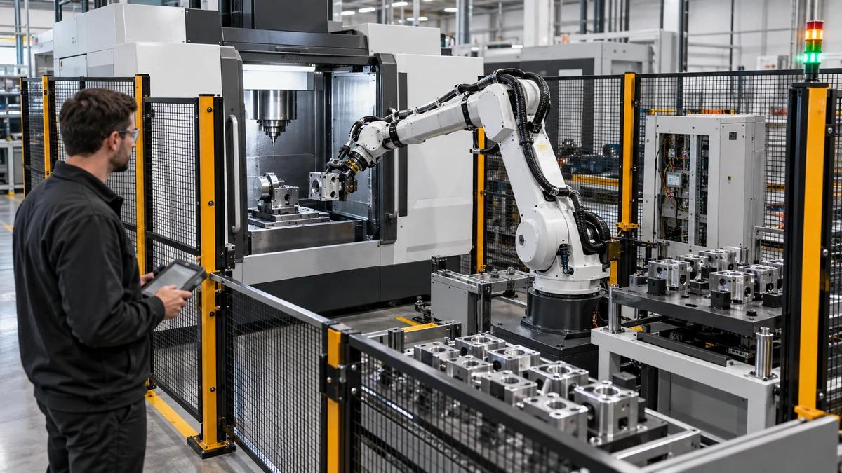
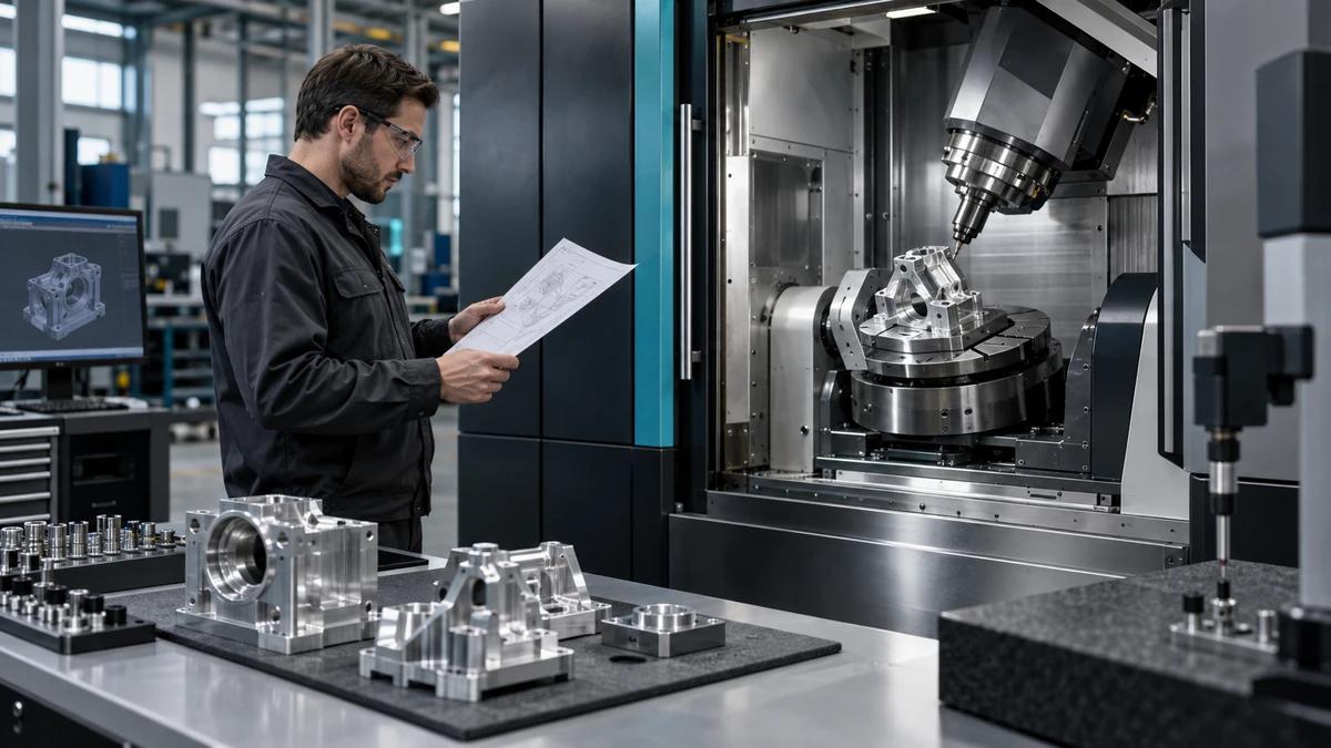
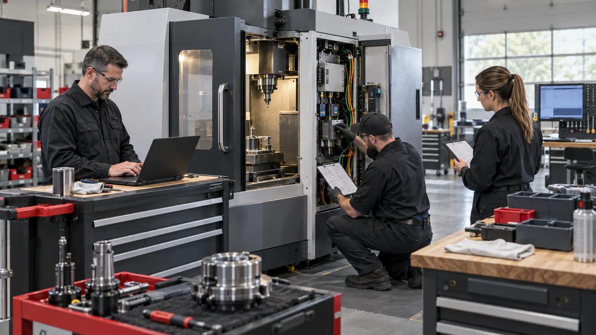
A China 5 axis machining center should be tested with more than one showcase part because access, kinematic accuracy, tool behavior, collision risk, and recovery change with workpiece geometry. Zhihe CNC uses three contrasting workpieces: an indexed prismatic housing, a simultaneous freeform blade, and a deep tilted mold insert.
The trial portfolio helps aerospace, medical, mold, energy, and complex-component teams see which machine and process controls are transferable and which are scenario-specific. The goal is not to create the most dramatic demo. It is to expose different failure signatures under controlled drawings, tools, programs, thermal conditions, and inspection.
Set One Shared Baseline Before the Three Tests
Freeze the machine configuration, controller and software versions, rotary arrangement, spindle, scales, probe, tool data, coolant, warm-up, kinematic calibration state, postprocessor, simulation version, backup, inspection method, and responsible owners. Record which parameters may be adjusted and what verification follows.
Zhihe CNC uses one shared baseline so differences between workpieces reveal application behavior rather than undocumented setup changes.
Workpiece A: The Indexed Housing
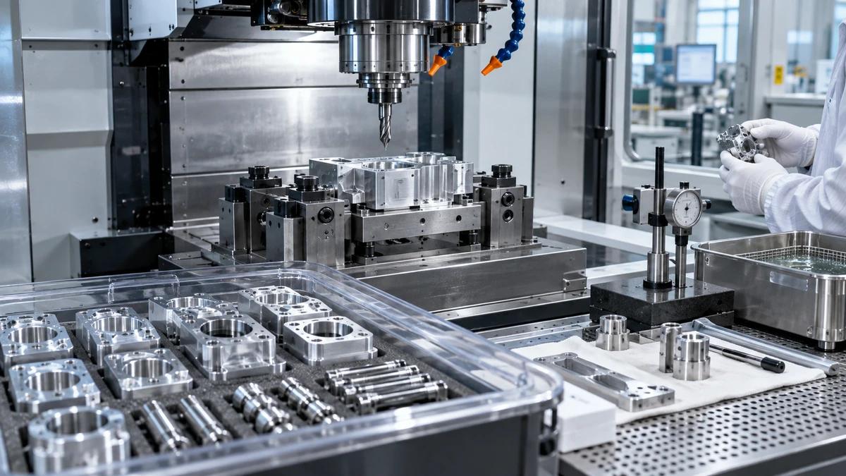
The housing tests datum strategy, three-plus-two positioning, face transitions, hole location, tool reach, fixture stiffness, probing, and the accumulation of rotary positioning error. Include bores, angled holes, sealing faces, pockets, and features that reference more than one orientation.
Score Housing Risk by Orientation Transfer
| Housing event | Evidence | Failure signature |
|---|---|---|
| Initial location | Probe and fixture record | Datum shift |
| Rotary index | Angle and feature result | Orientation-dependent error |
| Long tool | Runout and projection | Taper or vibration |
| Cross-face bore | Position and axis relation | Stacked kinematic error |
| Restart | Reference recovery | Unexplained offset change |
A China 5 axis machining center that passes easy top-face features may still fail when a critical feature crosses orientations.
Workpiece B: The Simultaneous Blade
The blade or impeller-like artifact tests continuous rotary motion, tool center point control, feed transformation, surface continuity, singularity management, postprocessor behavior, small-step motion, tool orientation, and inspection of freeform geometry. Use representative chord, twist, fillet, leading edge, trailing edge, and hub access.
Specify whether the test prioritizes form, surface, cycle, edge condition, or blended performance. One attractive surface does not prove all objectives. Preserve programmed and actual tool orientations at critical zones, identify axis reversals, and note where rotary speed or acceleration approaches practical limits. These observations help distinguish a geometry problem from a motion-planning or process problem.
Read the Blade's Failure Signatures
Facet marks can point to path resolution, smoothing, postprocessing, servo response, or inspection filtering. Witness lines may appear at orientation changes. Edge errors may come from tool condition, deflection, contact point, or excessive orientation. Near-singularity motion can create axis acceleration and surface disturbance.
Zhihe CNC recommends preserving the toolpath, controller settings, actual tools, machine logs where available, and a mapped inspection report so diagnosis remains evidence-based.
Workpiece C: The Deep Tilted Mold Insert
The insert tests collision clearance, short-tool access, steep and shallow surfaces, deep corners, holder interference, rest machining, chip escape, thermal sequence, finishing stability, and polishing handoff. Include areas that tempt the process toward unnecessary long tools or excessive rotary tilt.
This scenario often reveals whether five-axis motion reduces tool projection in practice or only in a clean simulation.
Compare the Three Workpieces Without Averaging Them
| Decision dimension | Housing | Blade | Mold insert |
|---|---|---|---|
| Primary motion | Indexed | Simultaneous | Mixed |
| Dominant risk | Datum transfer | Kinematics and surface | Access and collision |
| Key evidence | Cross-face features | Mapped form and finish | Reach and blend zones |
| Recovery test | Re-index and verify | Resume path safely | Restore tool and stock state |
| Buyer value | Setup reduction | Complex geometry | Shorter tools and finish control |
Do not collapse the result into one average score. A machine may be excellent for indexed housings and unsuitable for the simultaneous motion or mold access that actually drives the project.
Validate the Postprocessor as a Controlled Product
Record machine kinematics, controller functions, axis limits, pivot data, tool center point mode, rotary preferences, unwinding, singularity handling, feed behavior, safe positions, probing cycles, and post version. Validate representative moves in simulation and controlled dry or single-block stages.
Changes to the postprocessor require revision control and targeted revalidation. The post is part of the production system, not a one-time programming convenience.
Calibrate Kinematics Before Chasing Offsets
Define warm-up, reference state, probe qualification, artifact or method, rotary positions, measurement sequence, calculation, parameter authorization, verification, and expiry triggers. The ISO 230-2 search reference offers positioning context, while the project needs a complete five-axis calibration and feature plan.
Zhihe CNC recommends separating true kinematic correction from temporary part-offset compensation.
Build a Collision Envelope That Includes Recovery
Model the workpiece, blank, fixture, clamps, table, rotary body, spindle head, probe, tool, holder, extensions, neighboring setups, doors, and loading devices. Review approach, retract, tool change, probing, restart, and manual recovery positions, not only the ideal cutting path.
A China 5 axis machining center needs a safe plan for what happens after a tool alarm, program stop, power event, or interrupted simultaneous move.
Use Inspection That Can Explain the Error
Select features that separate location, orientation, form, size, surface, and transition. Record datum establishment, instrument, fixturing, environment, sampling, uncertainty, and alignment method. For freeform parts, preserve the comparison settings and avoid hiding local problems in a global best fit.
The ISO 10791 series reference can support machine-test planning, but part interpretation remains specific to the drawing and measurement strategy.
Rehearse Three Recovery Events
Stop after an indexed orientation, interrupt a simultaneous path at a controlled point, and replace a finishing tool during the mold test. For each event, record safe state, reference check, offsets, tool data, program restart, stock condition, verification cut or feature, and authorization to continue.
Zhihe CNC uses recovery rehearsal because stable production depends on returning to the baseline after ordinary disturbances.
Audit the Trial After the First Production Month
Compare planned and actual setups, tool projections, rotary use, collision warnings, program edits, calibration events, inspection differences, cycle losses, operator interventions, surface corrections, tool life, and recovery. Separate launch learning from recurring constraints.
What the China 5 Axis Machining Center Test Actually Proves
The three-workpiece test proves a bounded combination of machine configuration, kinematic state, controller behavior, postprocessor, fixture, tools, material, program, thermal sequence, inspection, and recovery method. It does not prove an abstract five-axis capability independent of those conditions.
A China 5 axis machining center earns a stronger decision when the same controlled baseline explains all three results. Zhihe CNC recommends linking every deviation to a failure signature: datum transfer, rotary positioning, simultaneous motion, surface transition, collision clearance, tool reach, thermal state, or restart. The diagnosis should lead to a verified correction, not an unexplained offset.
Before purchase approval, repeat one critical event on the China 5 axis machining center after a controlled restart or recalibration. The repeated result shows whether the team can recover the accepted process, which matters more to production than a one-time uninterrupted demonstration.
Know What Three Workpieces Cannot Promise
The portfolio cannot guarantee every future geometry, material, fixture, tool, post version, temperature, operator, or inspection result. It establishes a tested boundary and a repeatable method. New extremes of access, mass, rotary position, simultaneous motion, finish, or recovery may require targeted retrial, additional measurement, or a revised risk assessment before formal production release and customer approval.
FAQ
Why not use one complex demo part?
One part can hide scenario-specific weaknesses and makes it difficult to separate indexed, simultaneous, and deep-access behavior.
Does five-axis always mean simultaneous cutting?
No. Many parts benefit mainly from indexed positioning, while others require continuous coordinated rotary motion.
What is tool center point control?
It coordinates linear and rotary axes so the programmed tool point follows the intended path as orientation changes.
How often should kinematics be checked?
Set frequency from machine behavior, thermal conditions, collisions, maintenance, feature risk, history, and calibration results.
Can simulation eliminate collision risk?
No. Simulation reduces risk but depends on correct machine models, fixtures, tools, stock, parameters, and post behavior.
Which workpiece best tests accuracy?
Use features that represent the buyer's real datum, orientation, form, surface, access, and measurement risks.
Why test restart during simultaneous machining?
An interrupted path can create uncertain tool position, stock state, rotary orientation, and safe re-entry conditions.
Should probe results release the finished part?
Only when the agreed method, uncertainty, independence, feature coverage, and quality system allow that decision.
What must be frozen with the postprocessor?
Freeze version, machine definition, controller functions, axis rules, safe moves, tool-center modes, and validation cases.
Which files should accompany a Zhihe CNC five-axis inquiry?
Send representative part families, CAD, materials, blanks, fixtures, tools, tolerances, surfaces, volumes, inspection, and recovery needs.
Build the Three-Workpiece Test With Zhihe CNC
To evaluate a China 5 axis machining center, send Zhihe CNC one indexed part, one simultaneous geometry, and one difficult-access part with controlled CAD, drawings, materials, blanks, fixtures, tools, tolerances, surfaces, volumes, inspection, and restart expectations. Review the five-axis machining center range, the complete machine portfolio, and the contact page to define a representative trial.