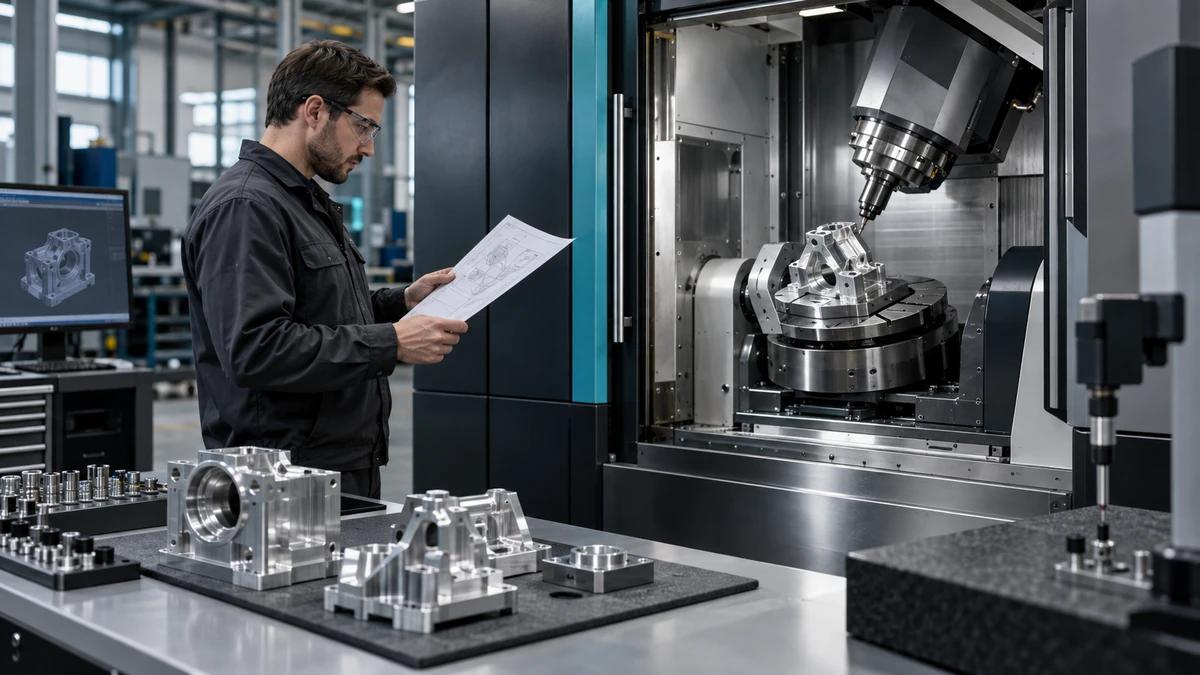
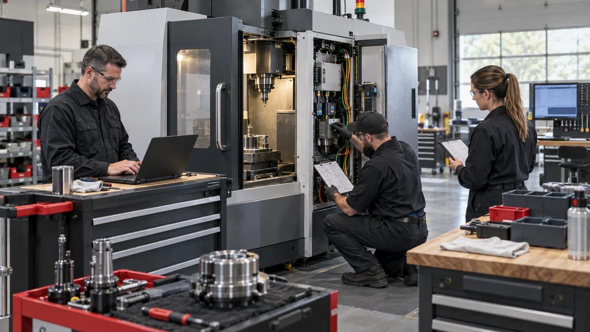
Answer the Motion Question First
A 5 axis machining center should be selected only after the buyer identifies which features need indexed 3+2 positioning and which genuinely require simultaneous motion. Zhihe CNC maps tool vectors, reach, holder clearance, surface transitions, datums and inspection before discussing machine specifications. Five available axes do not guarantee that every feature can be cut in one setup, with every tool, fixture or surface requirement.
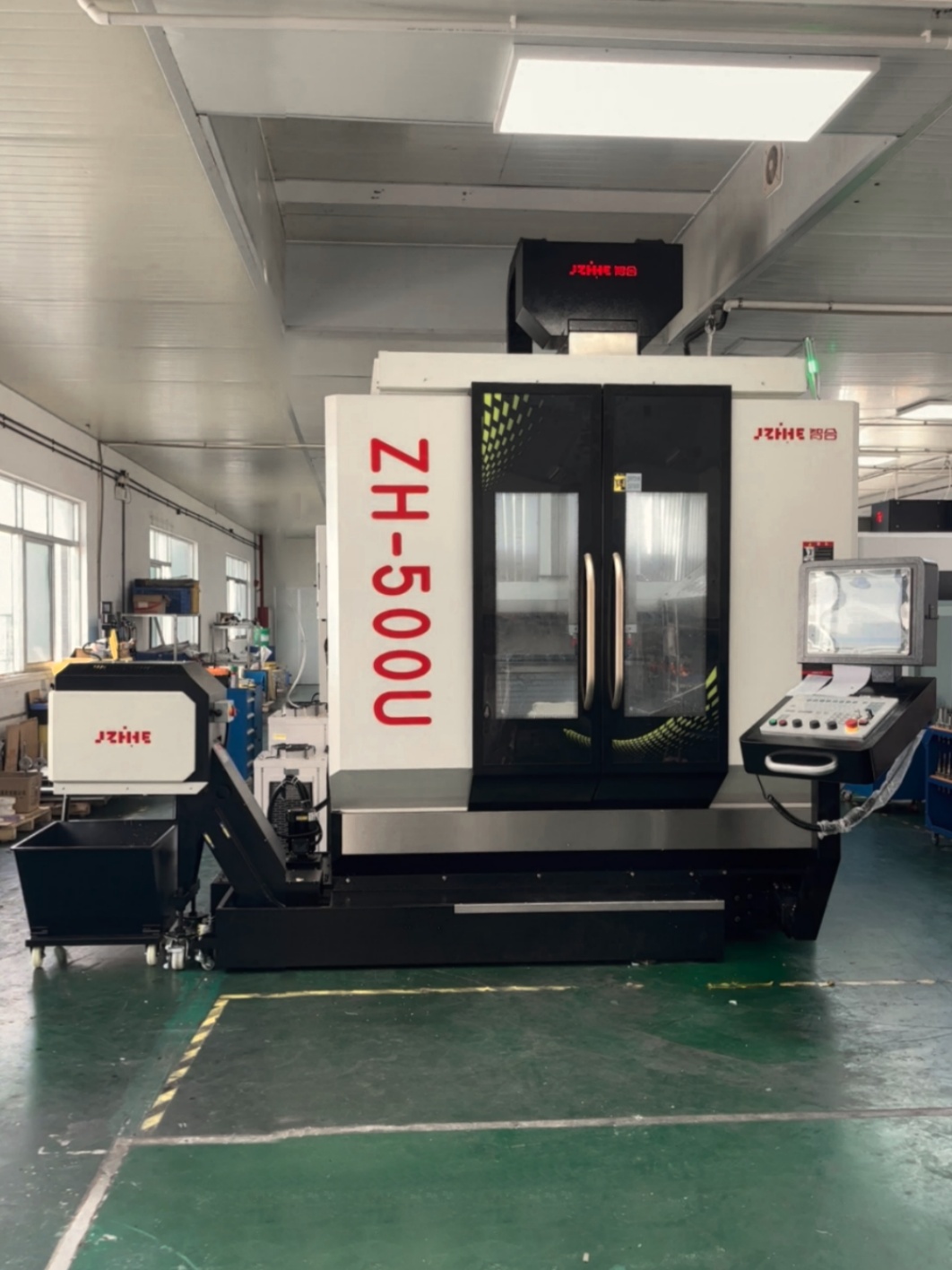
3+2 and Simultaneous Motion Compared
| Route | Useful when | Evidence to request |
|---|---|---|
| Indexed 3+2 | Several fixed tool orientations reduce setups | Rotary positions, fixture reach, datum and inspection result |
| Simultaneous motion | Tool vector must change through a surface or feature | Postprocessor, kinematics, collision check, tool path and raw surface data |
| Hybrid route | Most features are indexed with selected simultaneous regions | Feature-by-feature motion map and controlled transitions |
Choose the least complex route that releases the drawing. Added motion has value when it solves a named access, surface or handoff problem.
Build a Feature-to-Vector Map
For each critical feature, record tool direction, lead or tilt, reach, holder clearance, engagement, datum, surface limit and inspection method. Mark which axes move during cutting and which remain locked. A 5 axis machining center review becomes clearer when every motion claim points to a feature that requires it.
Map the Physical Envelope
Model workpiece, fixture, clamps, rotary table, supports, tools, holders, spindle nose, guards and chip space. Include loading and service positions. Zhihe CNC distinguishes nominal machine travel from usable reach because rotary orientation can move the part toward a limit or create a collision even when Cartesian coordinates appear acceptable.
The Digital Thread Check
- Freeze CAD and drawing revisions.
- Identify CAM strategy and feature ownership.
- Freeze postprocessor, controller and machine configuration.
- Store tool assemblies, holder geometry and rotary limits.
- Run collision and travel checks against the real setup.
- Keep the released program checksum and backup.
A software change can alter motion even when the part model does not change.
Separate Kinematics From Surface Finish
Machine motion, tool path, tool condition, holder, engagement, step-over, fixture, temperature and inspection all influence the result. Do not treat one surface as proof of every kinematic or product claim. Zhihe CNC records the declared conditions and compares raw data so a correction can be assigned to the correct lane instead of to a vague five-axis capability statement.
Evidence Map by Ownership
| Lane | Evidence | Primary owner |
|---|---|---|
| Machine | Rotary zero, axis limits, warm-up and calibration state | Supplier applications team |
| Digital | Postprocessor, controller, program, collision check and backup | CAM and controls |
| Physical | Fixture, tools, holders, support, chips and coolant | Production engineering |
| Quality | Alignment, gauges, raw data, corrections and release | Quality team |
| Service | Spares, training, maintenance and escalation | Supplier and buyer maintenance |
Design a Reach Trial
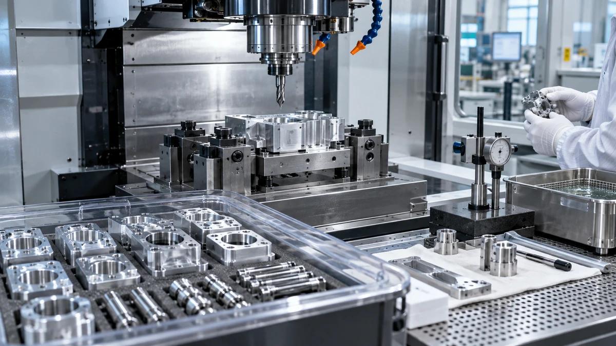
Include a tilted face, compound surface, deep feature, tight holder clearance, indexed bore and one controlled transition. Record rotary positions, tool vectors, program, fixture, tool state, temperature, measurement alignment and held-piece rules. The trial should expose the buyer's difficult geometry rather than use an attractive sample with unrelated conditions.
Protect Rotary and Fixture Limits
Document table load, center of gravity, inertia considerations, clamp state, support, lifting, datum cleaning and safe access. Confirm limits through the supplier's engineering review rather than extrapolating. For a 5 axis machining center, the fixture and rotary system form one physical chain; a weak interface can erase the setup advantage.
Make Corrections Traceable
Record measured feature, coordinate system, offset, tool, program revision, affected quantity, retest and release owner. Preserve the original file. Zhihe CNC recommends one reason per correction where practical so teams can distinguish motion, tool, fixture, thermal and inspection effects. Simultaneous edits create a result that is difficult to reproduce.
Measure Setup Reduction Honestly
Compare the existing and proposed routes using fixture preparation, loading, probing, cutting, handoffs, inspection, tool events, cleaning, maintenance, held work and released output. Do not claim savings without a declared part mix and time window. A multi-axis route may reduce datum transfers while increasing programming, tool verification or inspection work.
Audit the Support Chain
Ask who owns postprocessor changes, controller backups, rotary calibration, collision-model updates, application support, spare parts, training and escalation. State service region and response boundaries. A 5 axis machining center can depend on digital and service interfaces that are less visible than the machine, so they belong in acceptance and the quotation.
Write the Boundary of Proof
Name the tested geometry, material, fixture, tools, software, controller, machine state, environment, inspection and quantity. Product certification, fatigue, safety, downstream assembly and every future surface remain separate unless tested. Reopen affected evidence after part, fixture, tool, software, gauge, site or maintenance changes. Clear boundaries make the result reusable.
Buyer FAQ: 5 Axis Machining Center
What is the difference between 3+2 and simultaneous machining?
In 3+2 work the rotary axes position the part and remain fixed during cutting; simultaneous work changes tool orientation during the cut.
Does five-axis always mean one setup?
No. Fixture access, tool reach, inspection, chips, part support and feature requirements still determine setup count.
Why freeze the postprocessor?
Postprocessor, controller or configuration changes can alter the machine motion generated from the same CAM path.
What should a reach trial include?
Include representative tilted, deep, compound and clearance-limited features plus the buyer's inspection method.
How should collisions be reviewed?
Use the real machine configuration, fixture, rotary limits, tools, holders, part and released program.
Can one surface prove all machine accuracy?
No. The result is tied to motion, tools, fixture, temperature, program, inspection and declared conditions.
How should setup savings be measured?
Compare complete released-output routes, including programming, loading, probing, handoffs, inspection, holds and recovery.
How does Zhihe CNC define the right route?
Zhihe CNC maps each critical feature to the least complex motion, fixture and evidence route that releases it.
When should the motion baseline be reopened?
Reopen affected evidence after changes to part, fixture, tool, software, controller, gauge, site or maintenance state.
What should buyers send for review?
Send CAD, drawings, materials, surfaces, tool constraints, fixtures, volumes, inspection and service location.
Govern the Motion File as Production Data
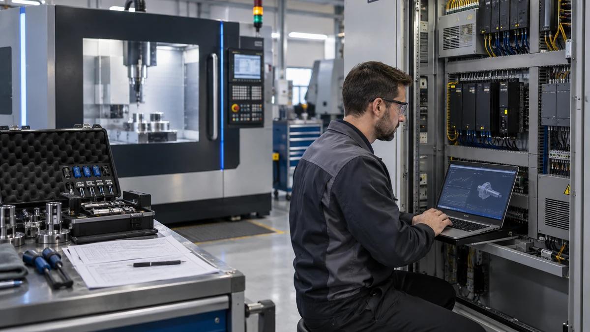
Store the approved CAD, CAM project, postprocessor, machine definition, controller configuration, tool assemblies, holder geometry, fixture model, rotary limits, collision settings, released program, checksum and inspection alignment under named ownership. Zhihe CNC recommends a change request that identifies the reason, affected features, verification evidence and release owner. This prevents an informal software update from changing motion without a corresponding review.
Backups should be restorable, not merely present. Test the handoff on the receiving system and record version, date and responsible role. Include the procedure for recovering rotary zero, offsets, probe routines and the released program after maintenance or control replacement. A digital thread is valuable only when production and service teams can identify the approved state.
Transfer One Feature Family at a Time
When a new part arrives, group features by tool vector, reach, holder clearance, surface requirement, datum and inspection. Compare the new groups with the accepted motion map. Reuse evidence where the condition is unchanged and reopen the lanes affected by new geometry, material, fixture, tool, software or gauge. This avoids both blind carryover and unnecessary full requalification.
For a 5 axis machining center, start transfer with a representative feature family and one boundary condition. Confirm programming, collision review, setup, cutting, inspection, correction and release before expanding the route. The staged approach gives Zhihe CNC and the buyer a clear evidence trail while keeping complex motion tied to specific manufacturing value. Name the owner, version, raw-data location and next review date at every transfer gate.
Review Human Access Around Complex Motion
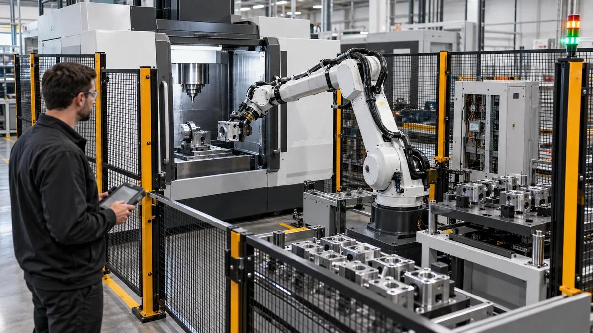
Map loading, fixture tightening, tool measurement, probe checks, chip removal, inspection, maintenance and recovery around the rotary positions used by the route. Confirm safe access with the delivered guards, doors and service clearances. A digital collision check protects programmed geometry, but it does not by itself describe every manual task or local risk during setup and maintenance.
Use the site risk assessment and supplier instructions to define controlled states, permissions and escalation. Record tasks that require special support, lifting or service intervention. Include these tasks in training and the production model. This keeps the motion decision connected to practical ownership and avoids treating sophisticated kinematics as a substitute for clear operating boundaries.
Open the Zhihe CNC Engineering Review
Send Zhihe CNC the controlled drawing or CAD model, material and stock condition, annual volume, batch mix, datum plan, fixture concept, tool constraints, inspection method, site utilities and service region. Review the Zhihe CNC machine portfolio, the company and manufacturing profile, and the engineering inquiry route. For 5 axis machining center, request a dated configuration, trial boundary, acceptance record, open-assumption list and named service owner before commercial approval.
Standards and Safety Context
The ISO 10791 machining-centre reference provides machine-test context, while the ISO 230-2 positioning reference provides an additional reference for testing or safeguarding. These references do not replace the buyer's drawing-specific acceptance plan, local risk assessment, product certification or legal obligations.