The Direct Buyer Answer
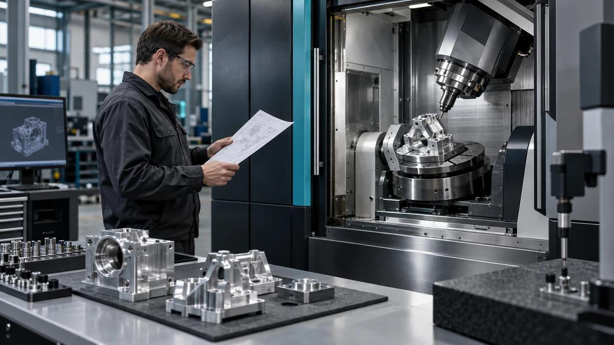
Impeller machining is a surface and access problem before it is a simultaneous-axis marketing problem. A 5 axis machining center for impeller parts must control blade passage, hub transitions, tool orientation, holder clearance, collision avoidance, scallop strategy, inspection and restart. Zhihe CNC uses a surface path atlas so buyers can judge the complete route on representative and boundary geometry.
Surface Path Atlas: Working Map
| Atlas layer | Question | Release evidence |
|---|---|---|
| Access | Can the cutter reach each passage? | Tool vector and holder check |
| Collision | Are tool, holder, part and fixture clear? | Simulation plus controlled prove-out |
| Surface | Is scallop and blend quality defined? | Marked surfaces and inspection data |
| Motion | Can the rotary path restart safely? | State record and recovery test |
| Quality | Can the result be measured? | Datum, gauge and raw-data plan |
Map the Blade Family
Divide the part into blade pressure side, suction side, leading edge, trailing edge, hub blend, shroud or root features. Record local radius, curvature, thickness, access direction and surface requirement. This map prevents the easiest face from standing in for the whole impeller.
Select one frequent geometry and one boundary geometry. Mark where tool orientation, holder projection or collision risk changes. Zhihe CNC recommends keeping the map with the program revision and inspection file.
Set the Datum and Fixturing Contract
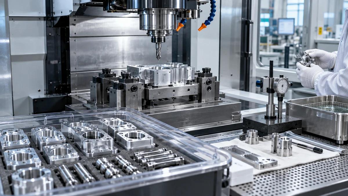
Define axis, balance, clamping, support, runout, probe access, loading orientation and reference surfaces. Impeller work can be sensitive to seating and rotary indexing. The fixture must preserve the datum while leaving the passage accessible and observable.
Repeat load and unload before cutting. Measure the same reference points after each load. A 5 axis machining center for impeller parts should prove repeatability of the setup, not only motion accuracy in an empty space.
Review Tool and Holder Geometry
List cutter form, diameter, flute length, holder, projection, runout, tilt range and replacement trigger. Check the holder at the deepest passage and near the smallest blade gap. Do not rely on cutter diameter alone; the holder and spindle nose can be the collision boundary.
Use a controlled prove-out with reduced risk and a defined stop authority. Record the program revision, tool identity, offset state and observed clearance. Preserve the approved tool assembly for repeat runs.
Define the Collision Envelope
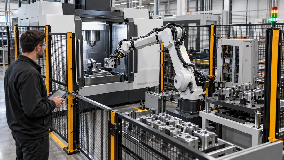
Include part, fixture, holder, spindle nose, probe, tail support and chip protection. State the simulation assumptions and where the operator must confirm the physical condition. A simulation is evidence of a model, not a substitute for a safe prove-out and local risk assessment.
Run a planned stop before the first difficult passage. Record machine state and restart steps. If a correction changes tool vector or holder, reopen the affected path and inspection evidence.
Choose a Surface Strategy
Separate roughing, semi-finishing and finishing. State step-over, tilt, feed, speed, tool condition, coolant and direction around each surface class. For blends and thin edges, define how the process protects form rather than simply quoting a small scallop value.
Measure marked locations and connect them to the path and tool state. Keep raw data and surface observations. Zhihe CNC uses a surface atlas to distinguish geometry error, tool wear, vibration and measurement variation.
Control Leading and Trailing Edges
Edges combine access, thin geometry, burr risk and inspection sensitivity. Define approach, exit, tool orientation, support, cleanup and edge acceptance. Review whether the same route is stable across the blade family or whether separate paths are required.
Inspect edge thickness and burr after cleaning. Record part identity and tool state. Do not smooth an unacceptable edge with undocumented hand work; record any permitted secondary operation and its owner.
Prove Rotary Index and Restart
Record rotary zero, indexing, clamps, coordinate transforms, probing, offsets and backup files. Use a controlled stop or planned tool event to test the restart route. The operator should know what is safe to retain, what must be re-probed and who authorizes release.
A restart test should include held-work identification, containment, correction, verification and disposition. This is particularly important when a long impeller program spans shifts or tool changes.
Build the Inspection Route
Define datum, balance reference, blade points, hub transition, edge features, sampling and raw-data storage. Large or complex surfaces may require specialized measurement, handling and queue time. Put that work in the capacity model.
Separate machine capability from measurement capability. If the buyer relies on an external lab or CMM, state the timing and handoff. A passed cutting trial without a repeatable inspection decision is incomplete.
Model Tool Life Across a Set
Track tool batch, run length, wear, replacement trigger, preset, runout and affected surfaces. Include a planned replacement in the trial. One fresh cutter can make a surface look stable while hiding the recovery work required in normal operation.
Compare before and after the event using the same marked locations. Keep accepted and held pieces identifiable. Zhihe CNC uses this evidence to set a conditional tool-life boundary rather than a universal promise.
Calculate Accepted Impeller Hours
Count loading, probing, cutting, indexing, tool changes, inspection, cleaning, holds, maintenance and recovery against released parts. State the mix and operator coverage. Spindle-on time alone does not describe a supportable impeller cell.
Test a representative and boundary part, then list the largest queue. It may be tool presetting, inspection, cleaning or engineering decisions. The atlas should point to an owner for that queue.
Evidence Ledger
| Failure signal | Do not assume | Check next |
|---|---|---|
| Edge burr | It is only a finishing issue | Tool exit, chip route, edge acceptance and cleaning |
| Blend mismatch | The machine is inaccurate | Datum, tool vector, wear and measurement alignment |
| Collision warning | Simulation is wrong | Model, holder, fixture, transform and prove-out state |
| Restart variation | The operator forgot a step | Backup, probe, offset, held-work and approval route |
Keep the Atlas Close to the Program
The surface path atlas should live with the released program, tool assemblies, simulation assumptions, inspection points and revision notes. A separate slide deck can explain the idea, but the operating team needs the controlled files at the machine and in the quality record.
Review the atlas after the first normal tool replacement and after any change to blade geometry, fixture, holder, probing or measurement. Close the difference with repeated evidence, an accepted limitation or a dated action owner. This keeps a complex path understandable after the original applications team leaves.
Separate Access From Capability
A 5 axis impeller machining trial should state whether the demonstrated result came from simultaneous motion, indexed positioning, special tooling, manual finishing or a combination. That distinction matters when a buyer moves from one impeller family to another. Zhihe CNC keeps the path, tool and inspection boundary visible so a capability statement remains tied to the tested geometry.
Before commercial release, ask the team to identify the first change that would reopen the 5 axis impeller machining evidence. It may be blade thickness, hub diameter, holder projection, material, balance requirement or measurement method. Record the owner and expected repeat test. This turns a complex technical conversation into a manageable operating rule.
Release by Geometry Family
The 5 axis impeller machining file should name the geometry family, material, tools, holder, path, inspection points and restart limits. A 5 axis impeller machining result is meaningful when those conditions are visible to the next shift and the next reviewer.
Keep the 5 axis impeller machining boundary beside the approved program. If blade thickness, hub transition or measurement changes, reopen the affected atlas layer and repeat the smallest sufficient trial rather than assuming the old result still applies.
Buyer FAQ: 5 axis impeller machining
What makes impeller work difficult?
Blade access, holder clearance, thin edges, blends, rotary motion, surface finish and inspection interact.
Is five-axis simultaneous motion always required?
Use it when the declared geometry and tool-access problem justify it; prove the path on representative parts.
What should a surface atlas contain?
Feature class, tool vector, holder, path strategy, marked inspection points and release boundary.
How should collisions be controlled?
Use model review, safe prove-out, stop authority, local risk assessment and restart evidence.
Why test a tool-life event?
It reveals whether tool replacement, preset, offsets and inspection can restore the approved route.
How should thin edges be released?
Define thickness, burr, cleanup, measurement route, sampling and permitted secondary work.
What belongs in an impeller capacity model?
Loading, probing, cutting, indexing, tools, inspection, cleaning, holds, maintenance and recovery.
How does Zhihe CNC handle restart?
Zhihe CNC records machine state, held work, correction, verification, disposition and owner.
Can one impeller prove all future parts?
No. State geometry, material, tooling, inspection and program limits for the tested family.
What should buyers send?
Send blade geometry, material, datum, edge limits, surface requirements, volume, tools and inspection route.
Bring the Decision to Zhihe CNC
Send Zhihe CNC the controlled drawings or CAD, material and stock, critical features, annual volume, batch mix, fixture concept, tool limits, inspection route, site conditions and service region. Review the Zhihe CNC product portfolio, the company and factory profile, and the engineering inquiry route. For 5 axis impeller machining, request a dated configuration, representative trial, acceptance boundary, open-assumption list and named support owner.
Reference Boundary
The ISO machining-centre reference and ISO machining-centre test reference offer machine-test or safeguarding context. They do not replace drawing-specific acceptance, local risk assessment, product certification, regulatory release or the buyer's operating procedures.