A batch drilling and tapping machine should be selected around the slowest repeatable step in the production cell, not around the fastest number in a machine brochure. The spindle may finish one part quickly, but output can still fall short when loading, tool changes, chip cleaning, thread inspection, fixture reset, or unplanned stops consume the rest of the shift.
This guide uses a capacity-diagnostic structure. It shows how to convert the drawing and production target into a time budget, locate the real bottleneck, choose the machine and fixture together, and verify the result with a controlled trial.
Define Output as Good Parts per Shift
Machine cycle time is only one part of capacity. The useful production measure is the number of accepted parts produced during available time.
Good parts per shift = available production minutes x expected utilization / total minutes per accepted part.
Total minutes per accepted part should include cutting, loading, unloading, air blow, chip removal, tool checks, offset adjustments, in-process inspection, planned maintenance, and the expected effect of scrap or rework. If four parts share one fixture, calculate the full fixture cycle and divide by the number of accepted parts, not simply by the number of stations.
| Time element | How to measure it | Why buyers miss it |
|---|---|---|
| Automatic machining | Program time from cycle start to cycle end | Quoted cycle may exclude optional stops or tool measurement |
| Load and unload | Observed operator time under realistic conditions | Prototype loading is often slower or less repeatable than the estimate |
| Fixture service | Cleaning, locating, clamping, and confirmation time | Chips under a datum can create both delay and dimensional loss |
| Inspection | Frequency multiplied by time per inspection | Thread gauges and positional checks are treated as separate quality work |
| Tool management | Tool life, replacement time, presetting, and offset entry | A fast tool changer does not eliminate worn-tool handling |
| Planned losses | Breaks, warm-up, cleaning, maintenance, and changeovers | Capacity is frequently calculated from the full shift length |
| Unplanned losses | Use measured history or a conservative launch assumption | New processes rarely start at mature utilization |
Use a Batch Drilling and Tapping Machine Bottleneck Map
If cutting time is the bottleneck
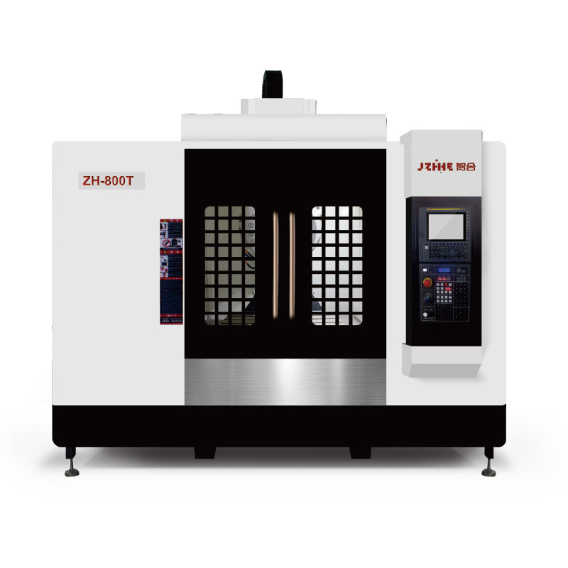
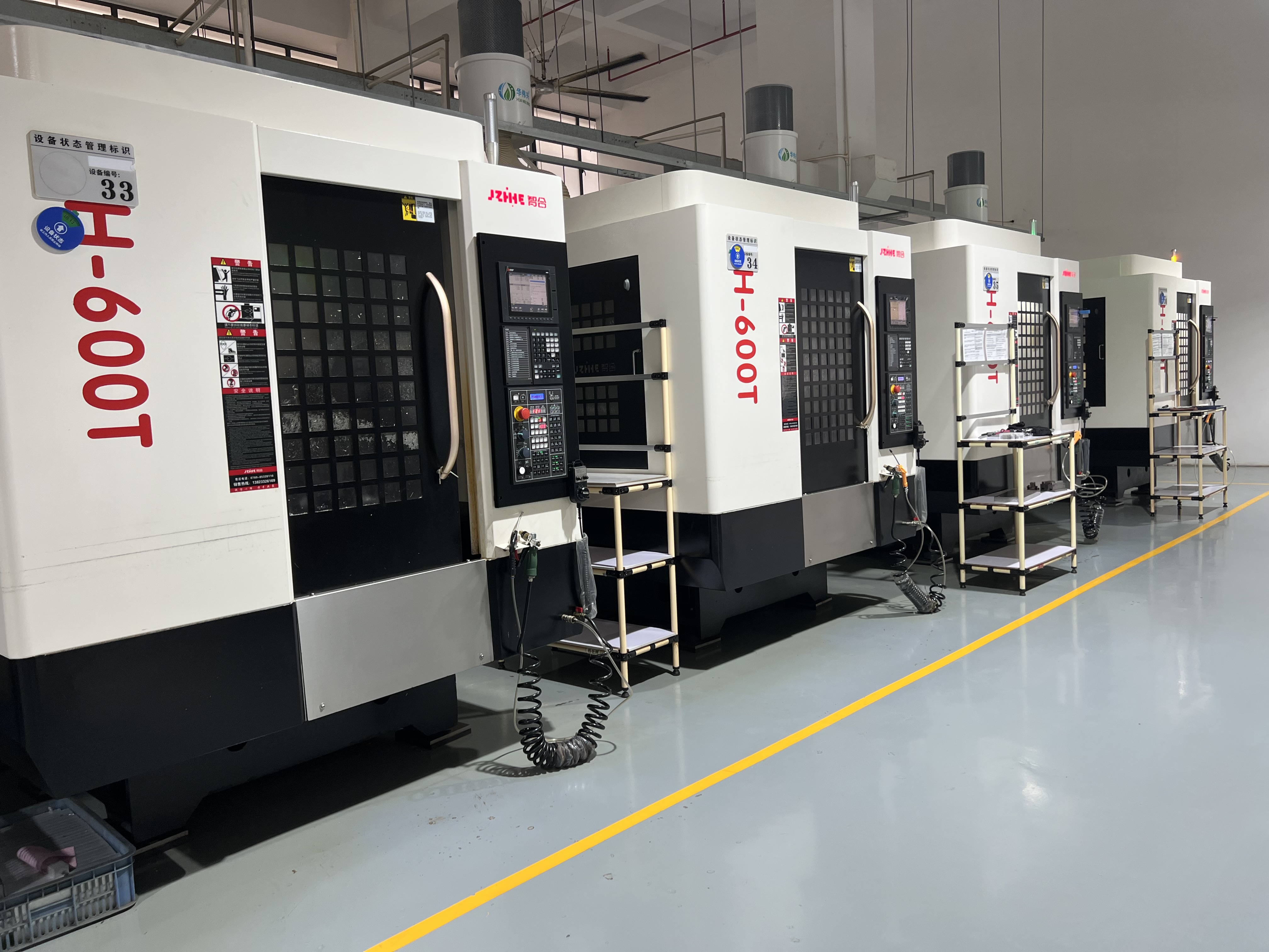
Review spindle speed and duty, axis acceleration, rapid traverse, toolpath, drilling strategy, tapping method, and tool-change sequence. Zhihe CNC publishes the ZH-600T with a BT30 spindle, 15,000 or 20,000 r/min maximum spindle speed, and 48 m/min rapid traverse on all three axes. These values are useful only after the tool diameters, material, hole depths, thread sizes, and cutting conditions have been defined.
If loading is the bottleneck
Improve the fixture and operator motion before buying spindle performance that will sit idle. Consider multi-part workholding, accessible clamps, mistake-proofed locating, hydraulic or pneumatic actuation where justified, and a loading method that keeps hands away from chips and sharp edges. Measure the process with the intended operator, part bins, gauges, and cleaning tools in place.
If inspection is the bottleneck
Separate process control from final acceptance. Identify which dimensions can be controlled through tool life and offsets, which require periodic gauging, and which require every-part verification. Thread depth, thread quality, hole position, and burr control may need different inspection methods. The machine quotation should support the control plan rather than assume inspection happens outside production time.
If chips are the bottleneck
Short-cycle aluminum work can generate a large chip volume. Confirm enclosure flushing, coolant direction, filtration, chip evacuation, fixture drainage, and access for cleaning. Chips left on locating surfaces turn a capacity problem into a quality problem.
Choose a Cell Pattern That Matches Product Mix
| Production pattern | Recommended cell logic | Main tradeoff |
|---|---|---|
| One stable high-volume part | Dedicated multi-part fixture, fixed tool set, standard inspection plan | High output but limited flexibility |
| Part family with common datums | Modular fixture base with interchangeable nests | Changeover discipline becomes critical |
| High mix and small batches | Flexible workholding, offline tool preparation, program control | Lower fixture investment but more setup variation |
| Unattended or extended operation | Automation, tool monitoring, chip control, error recovery | Higher integration and launch risk |
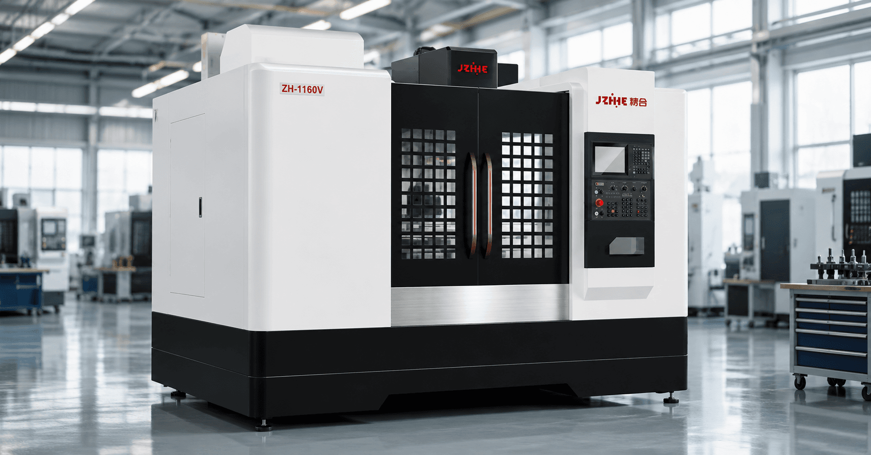
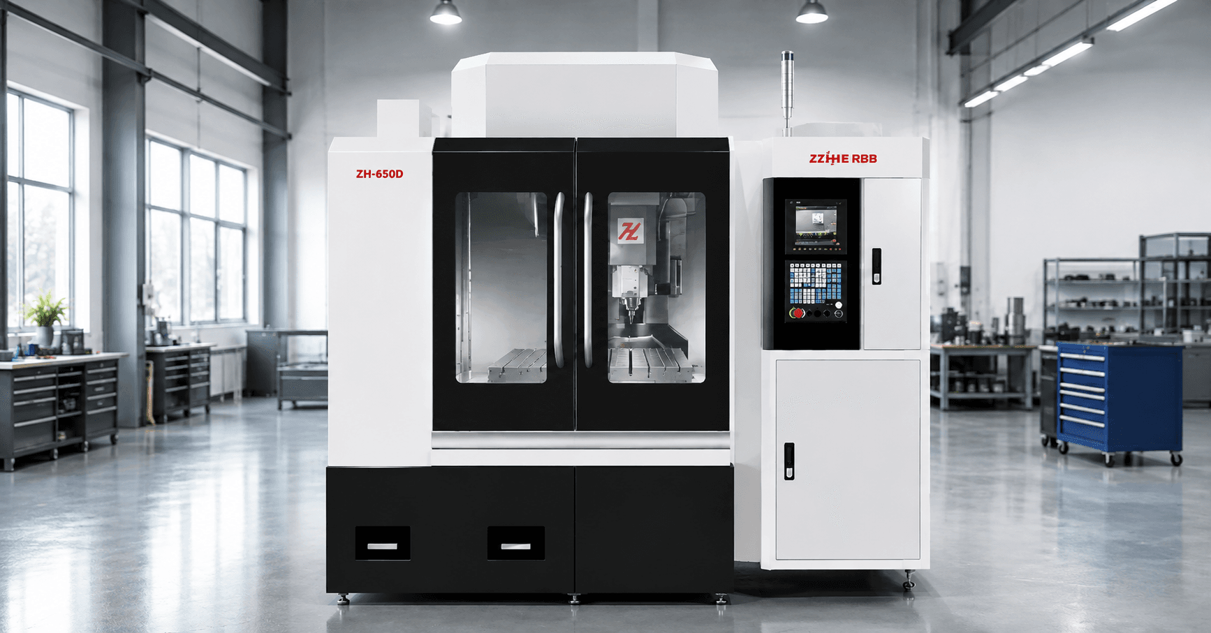
The Zhihe CNC drilling and tapping center series is positioned for high-speed drilling, tapping, and light milling of small-to-medium precision parts, including aluminum components, 3C parts, heat sinks, communication parts, and small brackets. Use this application range as a screening step, then validate the exact part and fixture envelope.
Build a Time Budget Instead of Guessing a Cycle
Create a worksheet with one row for every operation. Record tool number, operation, cutting time, rapid and approach time, tool-change time, coolant or chip-clear time, expected tool life, and inspection response. The result exposes where option spending can change output.
For example, a higher spindle-speed option may help small-hole work, while a better fixture may save more time on a part with a short automatic cycle. A larger tool magazine may reduce manual intervention for a mixed part family, while a dedicated magazine is unnecessary for a stable process using only a few tools.
Do not turn the time budget into a promise before trial cutting. Mark every value as measured, calculated, supplier-estimated, or assumed. Then replace assumptions during process validation.
Run a Trial That Tests Repeatability, Not One Showcase Part
A single accepted sample proves that the process can work once. Batch production requires evidence that it can continue.
- Freeze the drawing revision, blank condition, tools, fixture, program, and inspection method.
- Warm up and level the machine according to the agreed procedure.
- Run enough consecutive parts to expose tool wear, chip accumulation, thermal behavior, and operator variation.
- Record automatic time, load time, stops, tool changes, inspection time, scrap, and corrections.
- Inspect dimensions and threads in production order so drift is visible.
- Document the final parameters, offsets, tool life assumptions, maintenance actions, and open risks.
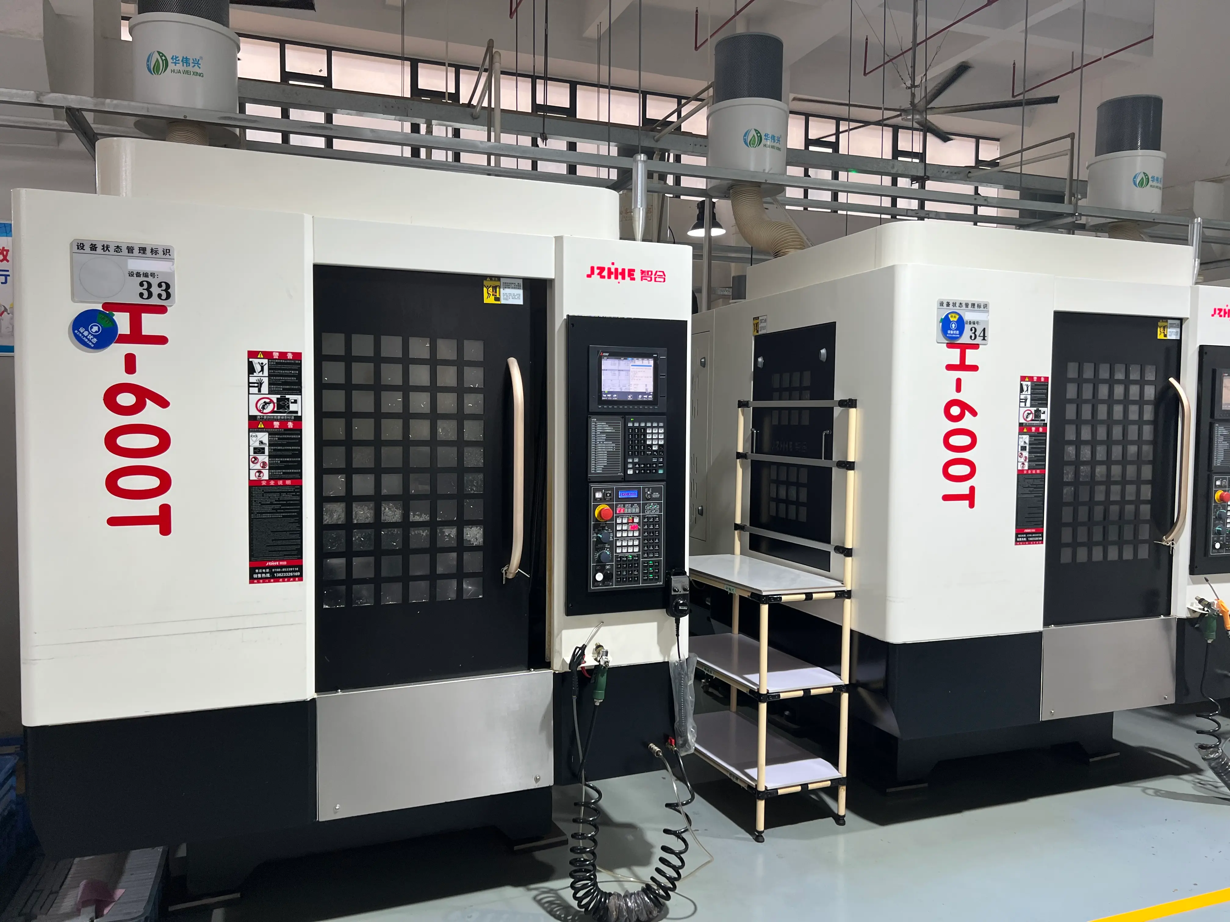
Zhihe CNC's published Vietnam aluminum-parts project describes a ZH-600T configuration with a high-speed spindle, fast tool-changing system, and custom fixture package. The company reports about a 28% cycle-time reduction for that project. The useful lesson is the configuration method: machine, fixture, and process were matched to the drawing. The percentage should not be treated as a guaranteed result for a different part.
Prepare the Production RFQ
Send the supplier the drawing, 3D model, material, blank condition, batch size, annual demand, shifts, target good parts per shift, current cycle breakdown, critical tolerances, thread requirements, tool list, fixture concept, inspection plan, automation expectation, and factory utilities.
Ask the supplier to return:
- A model and configuration recommendation with exceptions.
- A proposed process route, tool list, and fixture concept.
- A cycle-time breakdown with assumptions clearly marked.
- A trial-cut and acceptance plan.
- A training, maintenance, spare-parts, and support scope.
FAQ
How many parts should a trial run include?
There is no universal number. The run should be long enough to expose tool wear, chip accumulation, thermal change, loading variation, and the inspection frequency required by the process.
Is maximum spindle speed the best capacity indicator?
No. Output depends on cutting conditions, acceleration, tool changes, loading, inspection, chip control, utilization, and scrap. Compare the complete time budget.
When should a multi-part fixture be used?
Use one when the saved handling and machine-open time justify the fixture cost and when all parts can be located, clamped, cleared, and inspected consistently.
What should be measured after installation?
Track good parts per shift, automatic cycle, load time, inspection time, tool life, planned stops, unplanned stops, scrap, rework, and changeover time.
When is a VMC a better choice?
A vertical machining center may be better for larger workpieces, heavier cuts, larger tools, or a broader mix of operations requiring more torque or travel.
Request a Capacity-Based Recommendation
For a practical batch drilling and tapping machine proposal, send Zhihe CNC your part drawing, material, fixture size, thread and tolerance requirements, batch volume, shifts, target output, and current bottleneck. Use the contact page to request a process review, model recommendation, and controlled trial plan.