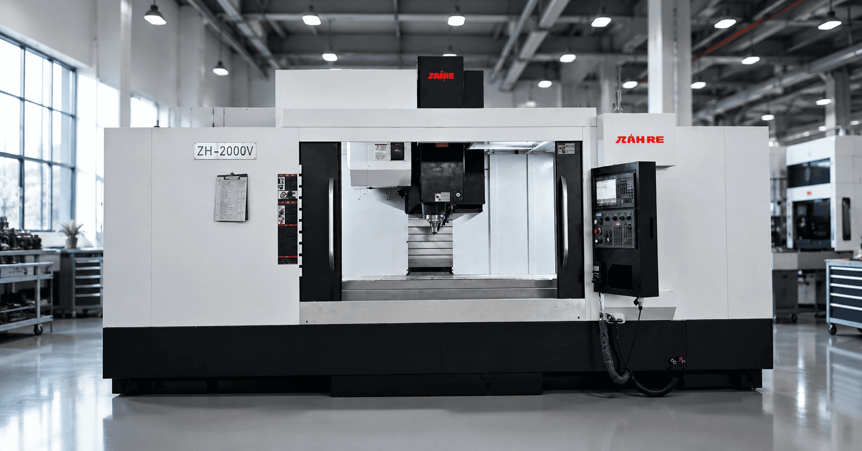
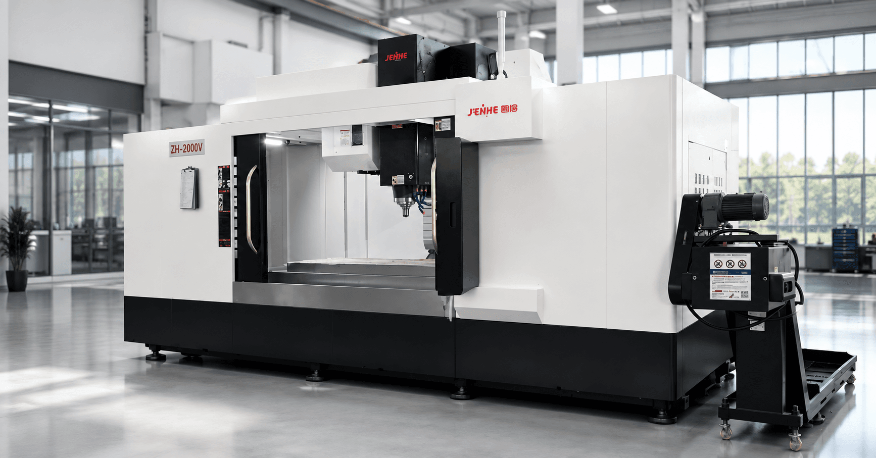
Robotics manufacturing is not one machining application. A robot program may include aluminum arm sections, steel mounting plates, cast-iron bases, stainless end-effector parts, gearbox housings, motor brackets, bearing seats, sensor mounts, and small precision hardware. These components vary in size, material, volume, and tolerance.
The right CNC machine for robotics components is therefore selected from the part family and production route, not from the industry label alone. A drilling and tapping center may suit small aluminum brackets. A VMC may handle plates and mixed prismatic work. An HMC can reduce setups on housings. A five-axis machine may improve access to complex arm, joint, or end-effector geometry. A gantry machine may be required for large bases and frames.
This guide shows how to translate robot-part requirements into a machine and process specification.
CNC Machine for Robotics Components: Segment the Part Family First
Group the parts by material, envelope, feature access, tolerance, annual volume, and setup route. Do not ask one machine to cover every robotics component unless the business case clearly values that flexibility. Select the least complicated platform that can make each priority group repeatably.
Zhihe CNC lists robotics among the industries served by its vertical, horizontal, gantry, drilling and tapping, milling, and five-axis product families. Its product overview can be used as a starting point, but the drawing should lead the recommendation.
Build a Robotics Part-Family Matrix
Create one row for each representative component and record:
- Part name and robot subsystem.
- Material, stock form, raw size, finished size, and weight.
- Critical datums, bores, bearing seats, mounting faces, threads, and finishes.
- Number of machined faces and angled features.
- Current setup count and inspection steps.
- Annual volume, batch size, changeover frequency, and target cycle.
- Current scrap, tool-life, handling, or capacity problem.
Sort the matrix into a few process groups. This prevents a high-volume bracket and a low-volume complex joint from distorting the same machine decision.
Typical Machine Fits for Robotics Components
| Machine layout | Typical robotics fit | What to verify |
|---|---|---|
| Drilling and tapping center | Small aluminum plates, covers, brackets, sensor mounts, hole-intensive hardware | Hole count, tapping, light milling load, tool changes, chips, batch volume |
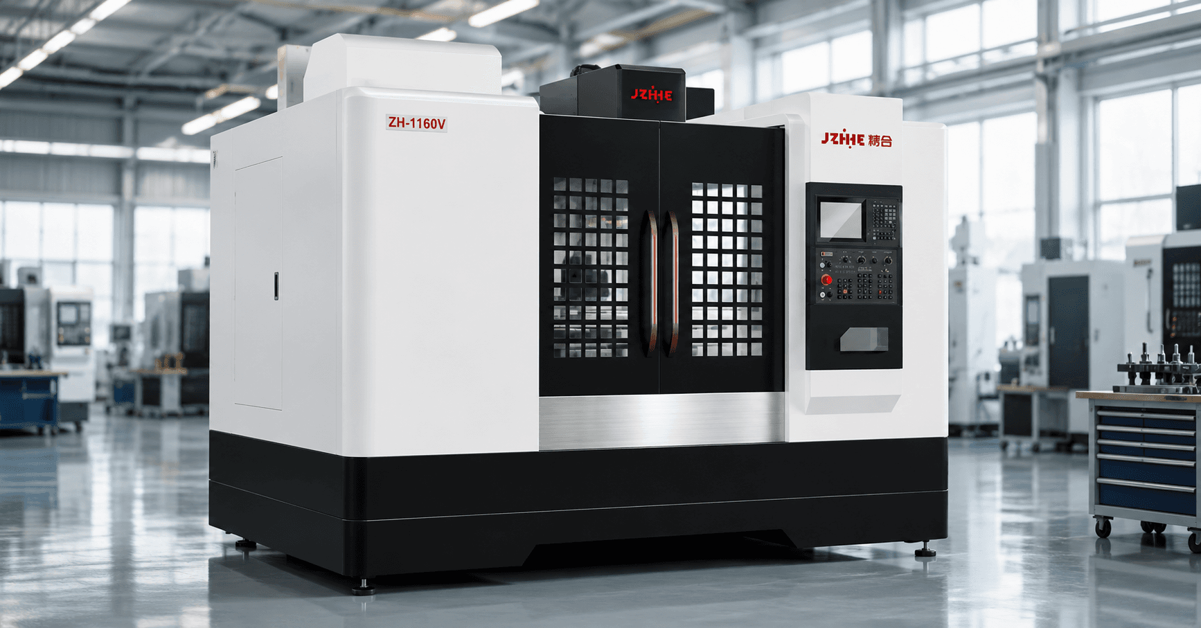
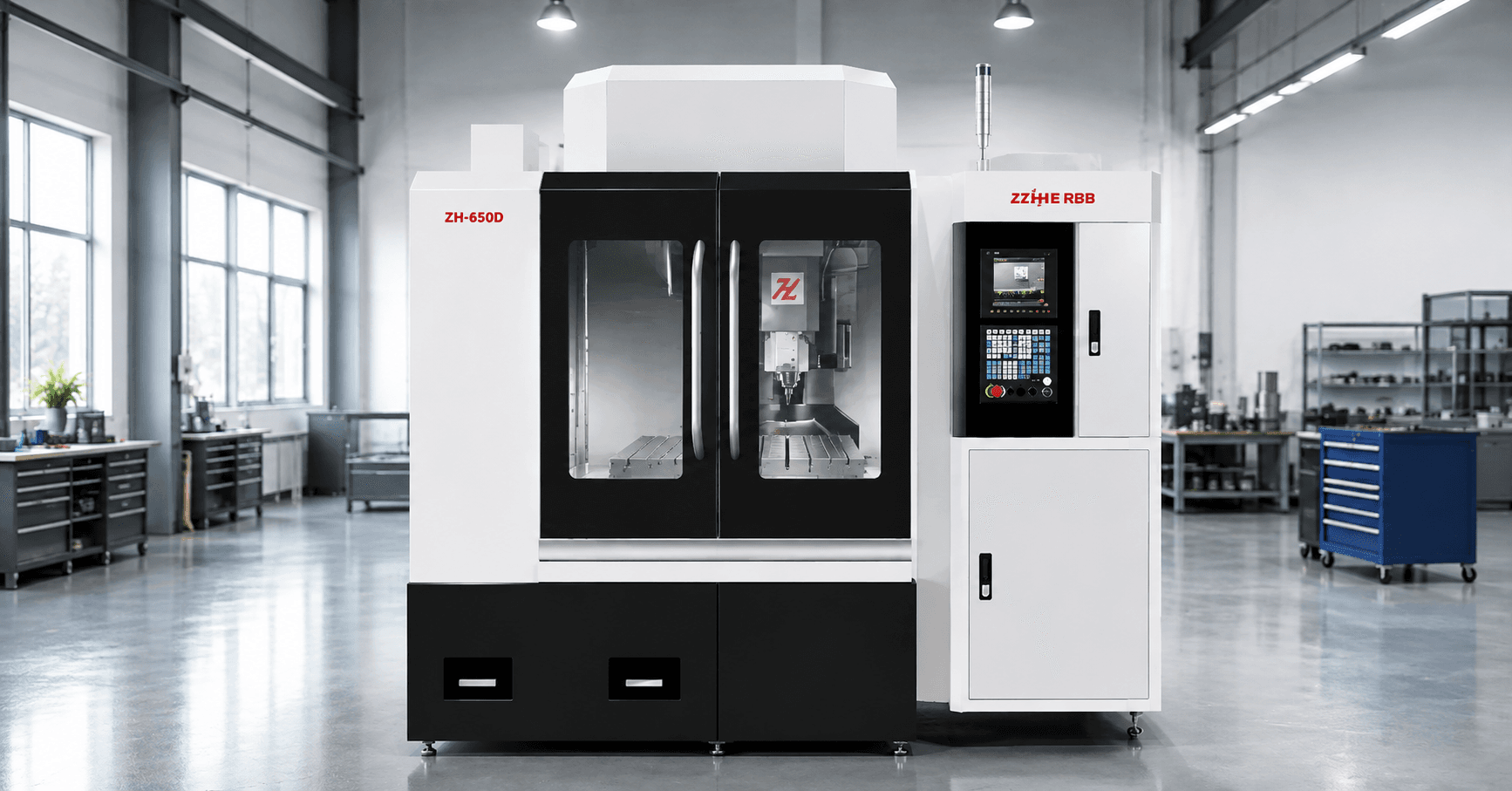
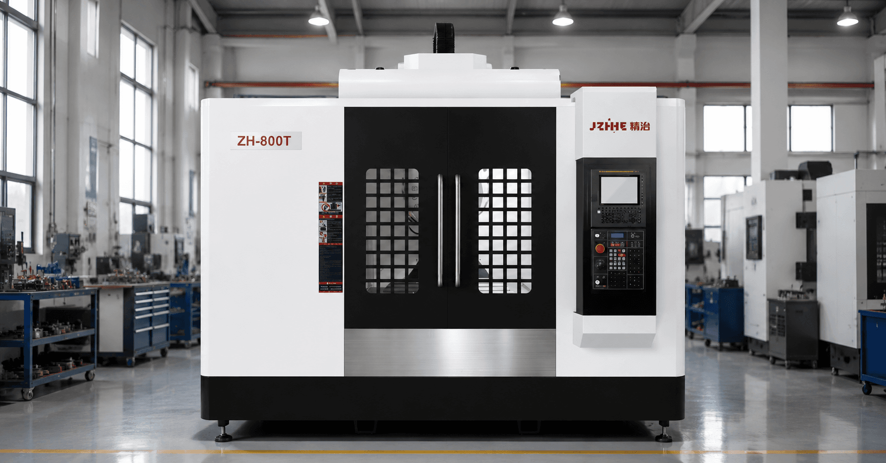
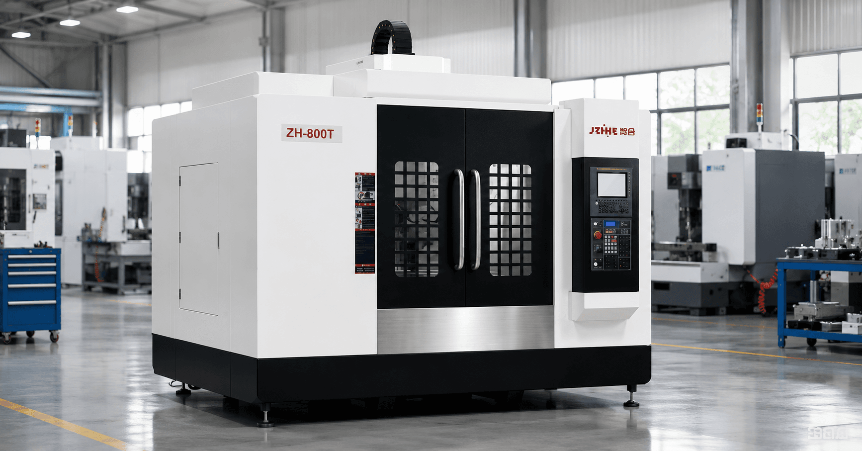
| Vertical machining center | Mounting plates, motor brackets, fixtures, arm sections, mixed prismatic parts | Travel, table load, spindle range, fourth-axis need, changeover flexibility |
| Horizontal machining center | Gearbox housings, joint bodies, hydraulic or pneumatic manifolds, multi-face castings | Rotary envelope, fixture, bore relationships, tool capacity, chip fall, pallets |
| Five-axis machining center | Complex joints, curved arm parts, angled interfaces, end-effectors, prototypes | Rotary access, kinematics, CAM/post, tool reach, collision control, calibration |
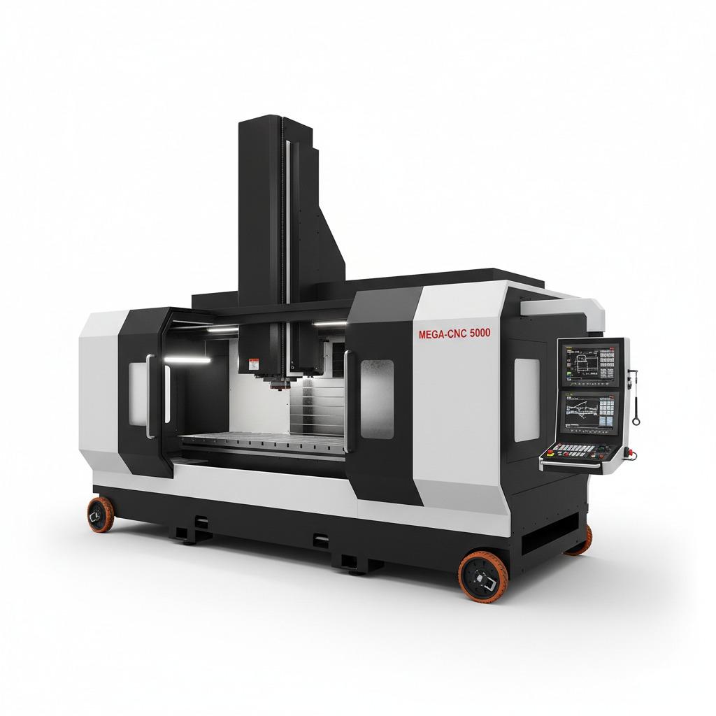
| Gantry machining center | Large robot bases, frames, long fixtures, oversize plates, heavy structures | Work envelope, load, bridge clearance, spindle duty, foundation, handling |
A versatile VMC can be a strong first machine for mixed work. It should not be forced to carry high-volume multi-face housing production if an HMC can remove repeated handling and datum transfer.
Material Mix Changes the Spindle and Chip Strategy
Robotics parts may use aluminum for low mass, steel for strength and wear, cast iron for damping and bases, stainless steel for corrosion resistance, and engineering plastics for covers or guides. Each material creates different cutting speed, torque, coolant, chip, filtration, and tool-life requirements.
List the percentage of spindle hours expected for each material group. A high-speed spindle selected for aluminum must still provide a workable range for steel operations. A heavy machine selected for steel bases may be inefficient for thousands of small aluminum brackets.
When one machine must process several materials, define cleaning and coolant practices that prevent chip mixing, contamination, and measurement problems.
Datum Relationships Matter in Robot Joints and Gearbox Housings
Bearing seats, motor pilots, gear bores, mounting faces, and bolt patterns may need controlled relationships. Repeated reclamping can add error and inspection work.
An HMC or five-axis setup can keep more features tied to one datum system. A fourth-axis VMC can also reduce setups for appropriate parts. Compare the actual face map and fixture access before adding rotary capability.
A proposed machine should be tested with the feature relationships that affect robot assembly, backlash, alignment, or service life. Do not accept a simple test block when the difficult part contains several bores and faces.
Workholding Must Support Flexible Changeover
Robotics suppliers often manage design revisions, prototypes, pilot builds, and growing production volumes. Fixtures need enough repeatability for quality and enough flexibility for changeover.
Consider modular plates, zero-point systems, standardized locating components, dedicated nests for stable high-volume parts, and documented clamping sequences. The best choice depends on batch size and revision frequency.
For thin aluminum arm components, control distortion and release movement. For cast housings, account for raw variation. For precision joint parts, keep chips away from locating surfaces and verify the part after unclamping.
Spindle, Tooling, and Magazine Capacity Follow the Route
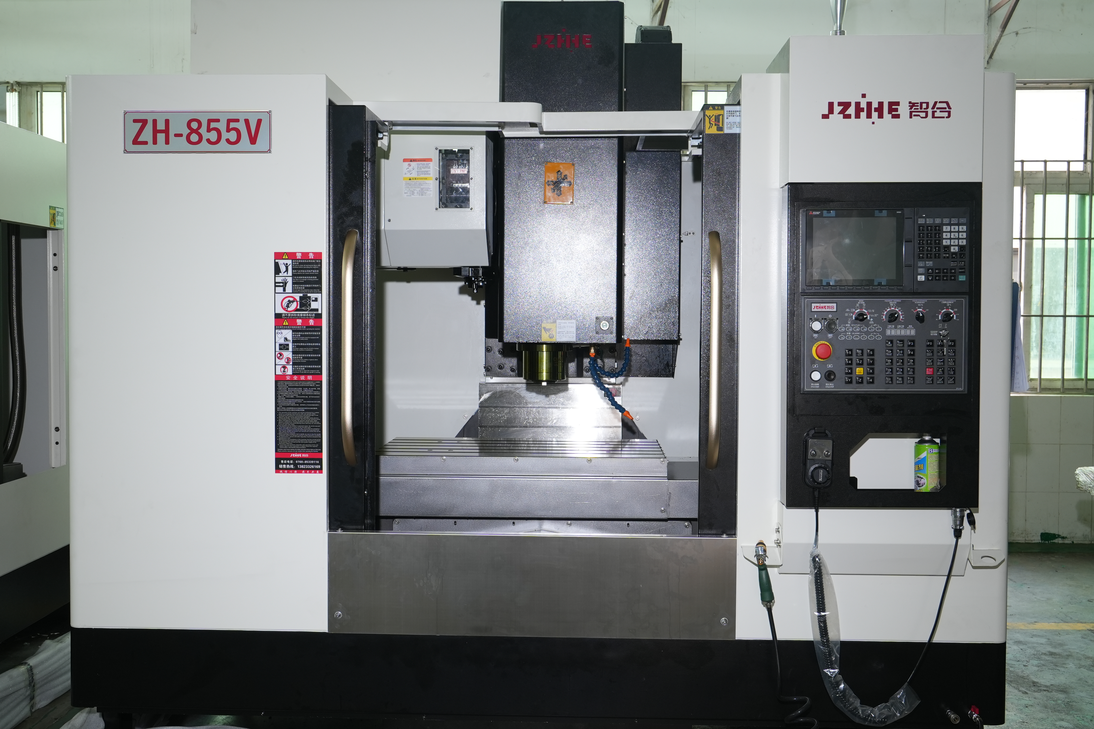
Build the tool list for each part family. Include roughing, finishing, spot drilling, drilling, tapping, boring, chamfering, probing, deburring, and backup tools. Mixed robotics work can fill a magazine quickly.
Review spindle speed and torque across the real operating range. Small aluminum tools may benefit from speed; steel roughing and larger drills require torque and stability. Long tools for deep housings introduce overhang and vibration risk.
Tool-life management and sister tools become valuable when the cell is expected to run unattended or across several pallets. Include tool measurement and broken-tool detection where the business case depends on automatic recovery.
Inspection Should Reflect Assembly Function
Machine acceptance should connect to the robot part's function. Identify the dimensions that influence bearing fit, gearbox alignment, motor location, joint squareness, interface repeatability, and final assembly.
Agree on inspection equipment and measurement timing. In-machine probing can verify setup and detect drift, but final acceptance may require a CMM, bore gauge, height gauge, surface tester, or other independent method.
Measure thin or stressed parts after they are released from the fixture. Record temperature and stabilization requirements for close-tolerance work.
Automation Is Valuable After the Process Is Stable
Robotics manufacturers may naturally consider robotic loading, pallet systems, automatic doors, part presence checks, probing, and in-process inspection. These systems work best when the fixture, tool life, chip control, program, and quality route are already predictable.
Define the unattended window and recovery method. What happens after a worn tool, missing blank, failed probe result, chip on a locator, or interrupted cycle? Automation without recovery planning can create longer downtime.
Zhihe CNC also supports custom machine and automation discussions. The request should include the part flow, loading orientation, buffer, takt target, quality checks, and operator responsibilities.
Capacity Planning: Prototype Flexibility vs. Repeat Production
A prototype shop values access, programming speed, visibility, and fast changeover. A repeat production line values spindle utilization, pallets, tool capacity, process monitoring, and low manual handling.
Estimate annual spindle hours for each part family. Add loading, setup, inspection, queue, cleaning, tool change, and planned maintenance. This shows whether one flexible machine, several dedicated machines, or a mixed cell is the better investment.
Use cost per acceptable part rather than cycle time alone. A faster cycle can lose its advantage if it requires more setups, inspection, operators, or rework.
Buyer Checklist
- Select three to five representative robotics parts.
- Group them by material, envelope, features, volume, and setup route.
- Mark critical datums, fits, bores, faces, and finish requirements.
- Compare VMC, HMC, five-axis, drilling/tapping, and gantry routes where relevant.
- Model the fixture, tools, rotary clearance, loading, and chip path.
- Build the complete tool and inspection list.
- Define automation only after the manual process and recovery plan are stable.
- Run a representative trial and document cycle, quality, wear, and intervention.
Common Buying Mistakes
- Using "robotics" as the specification. The machine must be matched to actual components.
- Buying one machine for incompatible part families. High-volume small parts and heavy bases may need different platforms.
- Ignoring design revisions. Flexible workholding and programming may be more valuable than a highly dedicated fixture.
- Automating an unstable process. Chips, tool life, part seating, and quality checks must be controlled first.
- Testing a simple sample. The trial should include the feature relationships and materials that create risk.
- Underestimating metrology. Machine accuracy, fixture repeatability, part release, and inspection method all affect acceptance.
FAQ
Which CNC machine is best for robot parts?
There is no single best layout. Match the machine to the part group: drilling and tapping for small hole-intensive parts, VMC for flexible prismatic work, HMC for multi-face housings, five-axis for complex access, and gantry for large structures.
Can one machine handle aluminum and steel robotics parts?
Often yes, but verify spindle speed and torque range, tooling, coolant, chip management, cleaning, and expected spindle-hour mix. A compromise machine should still perform the priority work well.
When does five-axis capability make sense?
It makes sense when it removes important setups, shortens tools, improves access, or machines complex contours. It should be justified by representative drawings and annual demand.
Should automation be ordered with the first machine?
It can be, provided the part flow, fixture, tool life, chip control, inspection, and recovery plan are defined. Otherwise, design the machine and cell for later automation.
What should be included in a trial?
Use the real material and difficult features. Record setup, tools, cycle, manual intervention, chip behavior, tool wear, measurements after unclamping, and any process limitations.
Request a Robotics Part-Family Review
To select a CNC machine for robotics components, send Zhihe CNC several representative drawings, material and volume data, current setup route, critical fits, factory constraints, and automation goals. Request a part-family matrix, machine recommendation, trial plan, and line-item quotation through the contact page.