CNC machine toolholder maintenance is easier to control when each tool assembly has a passport. The passport records the holder, taper, pull stud, collet or clamping element, cutting tool, balance state, presetting data, inspection result, storage position, and service history. Without it, a worn item can move from machine to machine and keep producing until a scrap event exposes the problem.
For a Zhihe CNC project, send the installation country, spindle interface, maximum speed, tooling family, automation arrangement, material, accuracy requirements, and maintenance capability. Zhihe CNC can provide configuration-specific spindle-side information for the selected machine. The buyer's tooling and process teams remain responsible for the holder standard, inspection program, acceptance limits, and safe use of tools.
Give Every Assembly a Passport
A tool number alone is not enough. The same holder can be assembled with different extensions, collets, pull studs, and cutting tools. The assembly changes mass, balance, stiffness, runout, and permissible speed. The passport should identify the complete assembly that was approved and tested.
| Passport field | Why it belongs on the record | Update trigger | Owner |
|---|---|---|---|
| Holder identification | Separates similar bodies and revisions | Replacement or rework | Tooling |
| Spindle interface | Confirms the correct mating form | Machine or standard change | Engineering |
| Pull stud or retention part | Controls clamping compatibility | Replacement or supplier change | Tooling |
| Collet, nut, or clamping element | Defines the actual assembly | Cleaning or replacement | Setup |
| Cutting tool and extension | Changes mass and reach | Tool change or process change | Programming |
| Balance and speed limit | Prevents unsafe or inaccurate operation | Component change or repair | Engineering |
| Presetting and offset data | Links the physical tool to the program | Preset or inspection update | Setup |
| Inspection and service history | Shows condition over time | Every inspection or repair | Maintenance |
The passport can be paper or digital, but it must follow the tool to the machine and back. A record that stays in a drawer is not controlling the assembly on the spindle.
Agree on the Spindle Interface Before Buying Holders
Confirm the spindle interface, taper size, retention form, orientation, drive keys or dogs, and maximum permissible speed from the machine documentation. Toolholder catalogs use related names and dimensional families, so purchasing should not choose by appearance or by what is already in the crib.
Record the machine serial configuration and the approved holder standard. If an adapter is proposed, define who owns its accuracy, stiffness, balance, and service. Adapters can solve a reach problem while adding interfaces that need inspection.
CNC machine toolholder maintenance begins before the first holder is purchased. A mismatch discovered at the spindle is a late and expensive place to correct a procurement decision.
Inspect the Taper and Face as One Interface
The spindle interface may transfer location and load through the taper, the face, or both, depending on the design. Inspect the contact pattern and condition using the machine builder's approved method. Do not assume that one shiny ring or one visible mark proves correct contact.
Clean surfaces can look acceptable while a small burr, corrosion patch, embedded chip, or polish pattern changes contact. Use magnification and approved checking tools where required. Record the location and extent of any abnormality, not only a pass or fail word.
The mating spindle surface also needs control. A damaged spindle taper cannot be corrected by replacing holders. The responsible service team should assess spindle condition with the correct instruments and procedure before production continues.
Understand Retention Force and Pull Studs
The pull stud or retention knob is part of the clamping system. Its geometry, material, hardness, thread engagement, and condition affect whether the holder is held correctly. A visually similar part from another source may not match the spindle's retention system.
The clamping mechanism applies force through the retention interface. Wear, contamination, incorrect assembly, or a damaged stud can reduce holding capability or change release behavior. The symptom may appear as movement, poor finish, vibration, or a tool change fault rather than an obvious break.
Keep the approved part number and supplier traceability in the passport. If a substitute is proposed, review the complete interface rather than only the external dimensions. The machine supplier and tooling specialist should define the acceptable configuration.
Visual inspection cannot prove that the spindle exerts the required retention force. Use the approved gauge or measurement method at a defined interval and record the result. The acceptance limit should come from the machine and tooling documentation, not from a generic workshop rule.
Measure with a clean, correctly assembled interface and a method that matches the spindle design. Confirm the gauge is calibrated and used by a trained person. A single measurement is useful, but trend data is better for deciding when service is needed.
ISO 10791-10:2022 addresses thermal deformation tests for machining centers. It is not a clamping-force procedure, but it illustrates why machine performance must be evaluated under controlled conditions. Use the specific machine and tooling instructions for the retention check.
If the force falls below the approved limit, stop using the affected interface until the responsible team evaluates it. Do not solve a retention problem by increasing cutting load, reducing speed without authorization, or ignoring the alarm.
Separate Cleaning From Repair
Cleaning removes chips, coolant residue, oil, and contamination from surfaces and features. Repair changes geometry through grinding, rework, replacement, or adjustment. The two activities need different authorization and records.
Use the approved cleaning method and avoid abrasive tools that alter a precision surface. Dry the holder and protect it before storage. Do not use a shop rag that leaves fibers or a solvent that harms seals, coatings, or labels.
After cleaning, inspect before assembly. A holder that was acceptable before cleaning may reveal damage that was hidden by residue. Record the result and route questionable items to a controlled quarantine area.
Balance the Complete Assembly
Balance depends on the holder, retention part, collet or clamping element, cutting tool, screws, and any adapter. Replacing one component can move the center of mass. A holder rated for a high speed with one assembly may not remain suitable with another.
Record the balance grade or method required by the application and the maximum speed approved for the complete assembly. Follow the tooling supplier's instructions for orientation and assembly. Do not add balancing screws or modify a holder without an approved procedure.
Sandvik Coromant's tool holding guidance explains the importance of the complete tool assembly, including balance and interface fit. Use the current manufacturer information for the actual product family.
Store and Transport Without Creating Damage
Storage should protect the taper, face, pull stud, cutting edges, and identification marks. Use the correct stand, cap, sleeve, or tray. Keep holders away from moisture, impact, metal dust, and loose fasteners. CNC machine toolholder maintenance includes this protected interval between uses.
Transport between the crib, presetter, and machine should be controlled. A loose holder rolling in a drawer can damage a taper or bend a small tool. A labeled position reduces the chance that a similar assembly is installed in the wrong job.
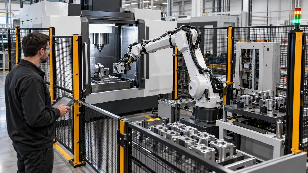
For automated tool magazines, confirm pocket compatibility, maximum mass, finger or gripper interface, orientation, and chip exposure. A holder that works manually may not be suitable for a high-speed matrix magazine. The machine-side and tool-side records should agree.
Inspect Wear and Damage at Useful Intervals
Inspection frequency should follow usage, material, spindle speed, tool mass, coolant, chips, and consequence. A high-speed finishing tool may need more frequent checks than a low-speed roughing assembly, while a rarely used special tool may deteriorate in storage.
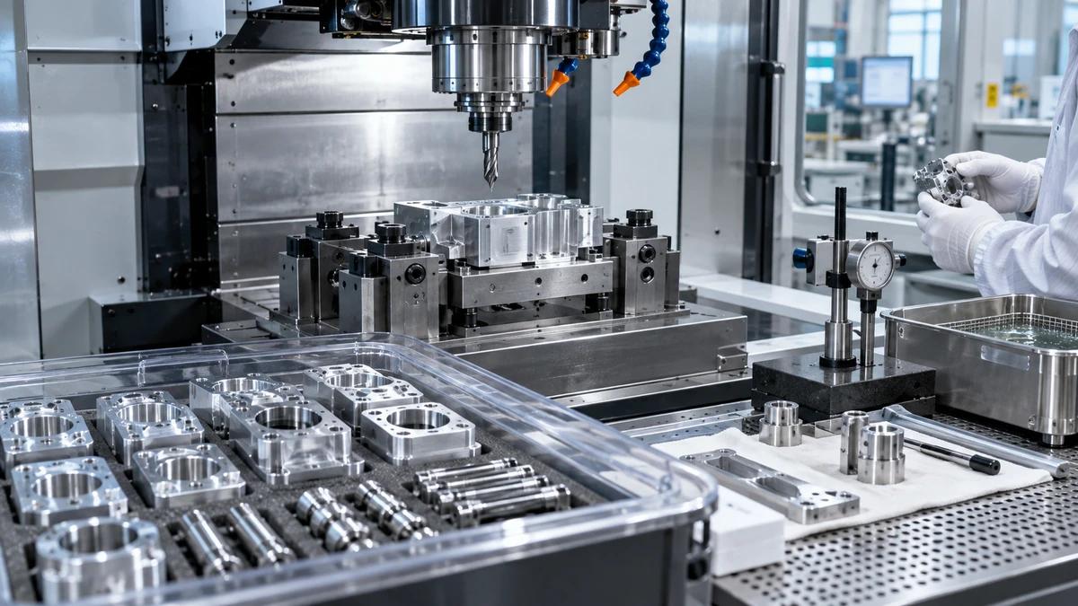
Look for impact marks, corrosion, galling, thread damage, pulled threads, cracked components, worn drive features, loose assemblies, and label loss. Use the approved instruments for taper contact, runout, balance, or clamping force where required.
| Finding | Immediate control | Engineering review | Typical disposition decision |
|---|---|---|---|
| Loose chip or light residue | Clean and recheck | Confirm method and assembly | Return after verified inspection |
| Taper or face mark | Quarantine | Assess contact and cause | Return, rework, or replace |
| Damaged pull stud | Remove from service | Check spindle and mating parts | Replace approved component |
| Low clamping force | Stop affected use | Inspect spindle and holders | Service spindle or holder |
| Crack or deformation | Quarantine immediately | Determine load and source | Replace, no field repair |
| Repeated runout or finish issue | Stop and isolate | Review assembly, spindle, and process | Corrective action before release |
The table is a routing aid. The actual disposition must follow the machine, tooling, and site requirements.
Write down what is measured, with which instrument, at what interval, by whom, and against which limit. Include the condition of the reference master and the method for handling an out-of-tolerance result. The release decision should be independent of production pressure. A documented CNC machine toolholder maintenance rule keeps an urgent job from becoming an informal exception.
Keep measurement records linked to the assembly passport. If a holder is reworked or a component is replaced, create a new revision or record so the old result cannot be mistaken for the current condition.
When a measurement is close to the limit, define the action before it fails. A trend can support planned service. A one-time reading taken after a visible problem may only confirm what the operator already suspected.
Control Presetting and Offset Data
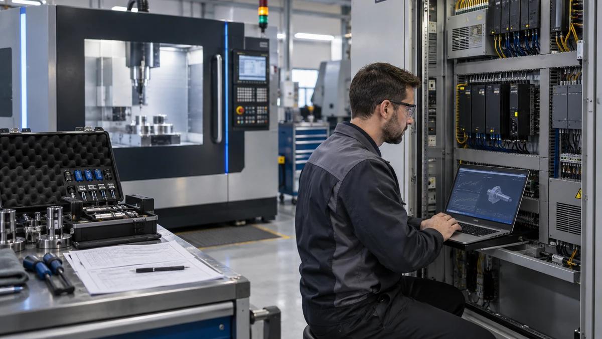
The physical tool and the digital offset must stay aligned. Presetting should verify assembly length, diameter, orientation, and any required runout or contact information. The setup person should confirm that the correct program, tool number, and revision are loaded. The same discipline belongs in CNC machine toolholder maintenance, where the physical assembly and its record must remain synchronized.
If a holder is replaced, the old offset may not describe the new assembly. Use a controlled update and, where required, a first-article or trial-cut check. The exact verification depends on the process and risk.
Automated tool data systems can reduce transcription errors, but they also need validation, backups, and access control. A barcode or chip on the holder is useful only if it remains attached and points to the correct record.
Link Toolholder Health to Process Capability
Toolholder condition can influence surface finish, dimensional variation, chatter, tool life, spindle load, and tool-change reliability. When a process drifts, do not blame only the cutting tool. Review the holder, retention, contact, balance, and assembly history.
Keep a short trend of relevant measurements and process results. A change in runout, clamping force, or vibration may precede a visible defect. The maintenance plan should connect those signals to a defined action.
This is especially important in high-speed or automated production. A small interface problem can become a machine stop or a damaged spindle. CNC machine toolholder maintenance is part of process control, not only a cleaning task.
Compare Repair, Replacement, and Standardization
The right response depends on the component, damage, cost, availability, and risk. A light residue may be cleaned; a worn taper may be reworked by an approved specialist; a cracked or deformed part should not be improvised. Purchasing should know which route is allowed before a failure occurs.
| Route | Use when | Required evidence | Main risk |
|---|---|---|---|
| Clean and return | Contamination is the only finding | Approved cleaning and recheck | Hidden damage or wrong method |
| Component replacement | Pull stud, collet, or nut is worn | Correct part and assembly check | Mixed or incompatible parts |
| Approved rework | The maker permits it and geometry is controlled | Procedure, measurement, and new record | Lost traceability or balance |
| Replace holder | Damage or wear exceeds limits | Quarantine and disposition record | Downtime and spare availability |
| Standardize fleet | Mixed brands create confusion | Interface and inventory review | Transition errors |
Standardization can reduce spare parts and training burden, but it should not erase a proven special tool without a review. OEM and ODM projects may need a common interface across several machine models; the buyer should define which parts are common and which are machine-specific.
Plan Spares and Lead Time Around Consequence
Spare planning should identify the items whose failure stops production, the items that can be replaced from local stock, and the items with long or uncertain lead time. The supplier can provide current information for the quoted scope, but the buyer should not assume that every component is immediately available.
Keep at least one controlled reference for critical assemblies and verify it before use. A spare that has been stored incorrectly or assembled with the wrong pull stud is not a reliable spare.
Record the purchase date, supplier, part number, and incoming inspection. If a substitute is accepted, document the approval and update the passport. This prevents an emergency replacement from becoming an uncontrolled change.
Ten Buyer Questions About CNC Machine Toolholder Maintenance
Does every toolholder need a separate passport?
Every controlled assembly should have a traceable record. The format can be digital or physical, but it must identify the complete assembly and its current revision.
Can I inspect the taper visually?
Visual inspection is useful but not sufficient. Use the approved contact, runout, or clamping-force method specified for the interface and application.
How often should clamping force be checked?
The interval should follow the machine and tooling instructions, usage, speed, and risk. Record the method, instrument, limit, and result.
Can a worn pull stud be reused after cleaning?
Only if it meets the approved condition and dimensional requirements. A damaged or questionable retention part should be quarantined and dispositioned.
Does balancing the holder alone balance the assembly?
No. The cutting tool, collet, retention part, screws, and adapters can all affect the complete assembly.
Is a shiny contact mark a good sign?
Not necessarily. Contact pattern, location, cleanliness, and the approved inspection method matter more than a general shine.
Can a damaged taper be repaired in the workshop?
Only through an approved process by a qualified provider. Improvised grinding or scraping can destroy the interface and invalidate the assembly.
What should happen after a crash?
Remove the affected assembly from service, inspect the spindle and holder under the approved procedure, and do not restart production until the responsible team releases it.
How does storage affect tool life?
Moisture, impact, dust, and loose storage can damage precision surfaces. Use the specified stand, protection, and labeled location.
Which spindle and tooling details should I send to Zhihe CNC?
Send the spindle interface, maximum speed, tool families, automation plan, inspection capability, and any existing toolholder standard for review against the selected machine.
Make the Interface Passport Part of Daily Work
Review the Zhihe CNC machining-center portfolio and the company and manufacturing profile. Then use the engineering contact route to share the spindle, tooling, automation, and maintenance plan.
Strong CNC machine toolholder maintenance does not depend on one careful operator remembering every detail. It gives every assembly a traceable condition, an approved configuration, a release rule, and a clear owner. That is how the interface stays trustworthy when production speed and tool variety increase.