Buyer Answer: Follow the Handoff
Zhihe CNC maps wind-turbine component machining through load envelopes, datum ownership, bore relationships, tool access and evidence-led handoff. The useful decision is whether the proposed route can preserve the feature relationships that matter after support release, inspection and downstream handoff.
Component Teardown Memo
| Evidence lane | Record | Decision owner |
|---|---|---|
| Raw part | Mass, material, stock and lifting state | Incoming quality |
| Setup | Fixture, support, datums and access | Manufacturing engineering |
| Features | Bores, faces, patterns and tools | Applications and quality |
| Handoff | Inspection, cleaning and open issues | Assembly or service |
Start With the Component Family
A wind-turbine component list can hide very different risks. Separate hubs, adapter plates, bearing seats, flange rings and service brackets by mass, lifting points, datum quality, bore relationship and downstream owner. The machine decision should begin with the hardest representative family, not the easiest drawing.
A CNC machine for wind turbine components is useful only when its working envelope, support route and inspection plan match the buyer’s actual boundary part. Zhihe CNC recommends naming the common component, the largest part and the feature that controls assembly before comparing travels or spindle power.
Write a Load Envelope Before a Layout
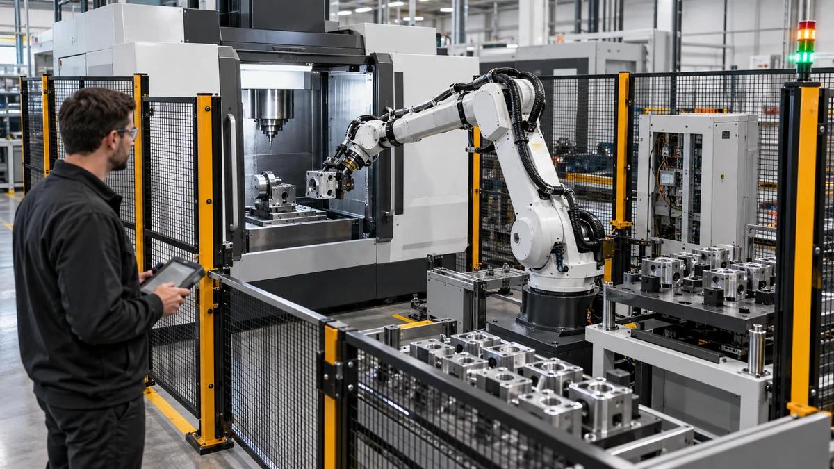
Record mass, center of gravity, lifting method, support points, fixture height, swing clearance, floor access and permitted contact marks. A large part can fit inside a nominal travel envelope yet fail at loading, chip removal or inspection. Treat handling as part of the machining route.
Use a simple envelope drawing with raw, clamped, rotated and released states. Put the responsible owner beside each assumption. When a crane, pallet or fixture changes, reopen the envelope instead of carrying a convenient first estimate into production.
Give Every Datum an Owner
List casting or forging references, created datums, probing points, functional bores, bolt circles and inspection alignment. State who establishes each reference and when it is checked. A datum without an owner becomes a debate after the first deviation.
Keep the raw-part coordinate, machining coordinate and inspection coordinate visible in one record. The purpose is not to force one universal frame; it is to make every transformation explainable when a component moves between teams.
Protect Bearing and Bore Relationships
Bearing seats, pilot diameters and mating bores should be treated as connected features. Document approach, support, tool condition, probing, temperature context and the free-state inspection method. Local size readings do not prove that a bore is aligned to its mating face.
Run a controlled reload or interruption and repeat the key reference. Preserve raw data by component identity. This reveals whether the route survives ordinary production events instead of only a carefully staged first piece.
Hub-to-Handoff Walk-Through
- Identify the raw part and load envelope.
- Approve datums, support and lifting.
- Verify access, tools and coordinate frames.
- Machine connected bores, faces and patterns.
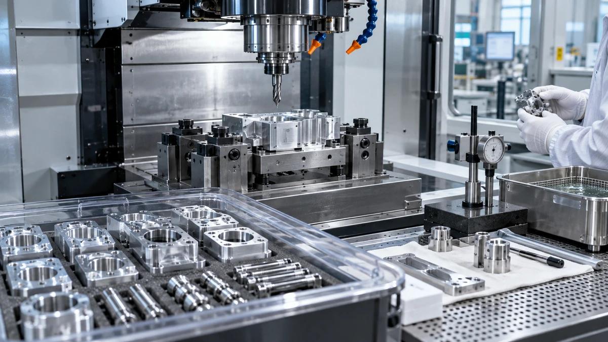
- Inspect in the declared support state.
- Transfer the released component with exclusions.
Choose Access From the Deepest Feature
Map deep bores, bolt circles, cross holes, pockets and underside faces. Check holder clearance, tool length, rotary limits and the space needed for cleaning and measurement. A short tool that cannot reach a protected feature is not a practical solution.
Make the access review specific to the fixture and released configuration. Zhihe CNC prefers a documented tool assembly and holder check over a brochure statement about maximum reach.
Control Flange Faces as Interfaces
Classify faces as sealing, locating, bearing, bolting or noncritical. For each class, define stock allowance, finish route, edge treatment, inspection method and downstream owner. This avoids treating every visible surface as if it carried the same assembly consequence.
Keep surface and flatness claims tied to a drawing revision and measurement setup. If a coating, grinding or field fit follows machining, show the allowance and handoff rather than attributing the entire result to the CNC machine.
Make Chip and Coolant Behavior Visible
Large cavities and horizontal faces change how chips, coolant and wash-down behave. Observe a full representative run with normal tool changes. Record accumulation points, cleanout access, operator protection and the state in which the part enters inspection.
OSHA machine-guarding guidance provides general hazard context, but the delivered enclosure, access points, lifting route and local procedures require a site-specific risk assessment. Include that boundary in the project review.
Build a Feature Evidence Board
Use one board to connect raw-part identity, fixture, program, tools, probing, inspection, accepted quantity, holds and open questions. The board should make it possible to answer what changed without searching through unrelated emails or screenshots.
A useful board has an explicit reopen trigger: drawing change, blank supplier change, fixture change, tool assembly change, program revision, gauge change or site condition change. Keep the prior baseline intact.
Released-Component Evidence Matrix
| Gate | Minimum record | Outside scope |
|---|---|---|
| Incoming | Identity, stock and lift state | Foundry approval |
| Machining | Program, tools, datums and raw data | Field loading |
| Inspection | Support, alignment and results | Fatigue life |
| Handoff | Quantity, holds and exclusions | Commissioning |
Rehearse the Handoff to Assembly
Create a controlled scenario where a bore, face, bolt-circle relationship or cleaning state is held. Record containment, affected quantity, correction, retest, disposition and the person who communicates with assembly or field service.
This exercise tests information flow without claiming that machining evidence proves turbine performance. Keep structural, bearing, bolt-preload, balance and site commissioning decisions separate unless separately validated.
Count Released-Component Hours
Include receiving, lift preparation, setup, probing, roughing, finishing, tool events, chip removal, inspection, holds, maintenance and released components. State staffing, batch mix, gauge availability and planned downtime. Spindle-on time alone is not capacity.
Compare the common component with the boundary component over a declared window. The queue that controls accepted output may be handling, inspection or cleaning rather than cutting, and the quotation should show that constraint.
Audit a Change Before It Ships
When a blank, support, tool, program, bore, face, gauge, lifting method or site utility changes, identify affected evidence and define the smallest sufficient revalidation. A dated change note should name revision, trial quantity, reviewer and effective date.
Do not let a successful correction erase the conditions that made the original result meaningful. Preserve the baseline and link the new record to the component family and installation destination.
Close With a Handoff Memo
Summarize component revision, material, raw-part state, fixture, datums, tools, program, inspection, accepted quantity, open issues and service route. Attach the documents needed to reproduce the released state after installation.
The final memo for a CNC machine for wind turbine components should state what machining released and what remains outside the claim: balance, fatigue, bearing life, bolt preload, corrosion protection, commissioning and grid performance.
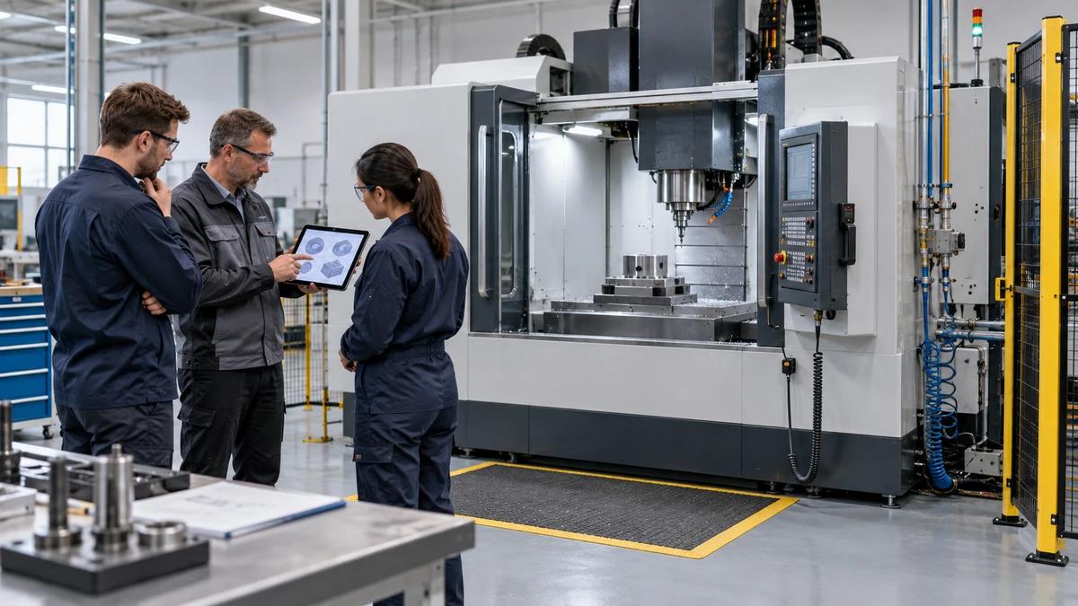
Ask the team to walk the raw component from unloading through inspection and assembly. The useful questions are ordinary ones: where does a sling touch, where does a chip collect, which face is protected, and who signs the next handoff? Writing those answers beside the machine configuration makes a large-component project easier to price, install and support. Keep a photo or sketch as an orientation aid, while the controlled drawing and inspection record remain the controlling evidence.
For CNC machine for wind turbine components, keep the machine decision attached to a real part family, a dated trial and an acceptance owner. A CNC machine for wind turbine components review is strongest when the buyer can see the setup, the evidence and the limits together. That is how CNC machine for wind turbine components becomes a repeatable procurement conversation instead of a generic machine claim.
Wind Component Buyer FAQ: CNC machine for wind turbine components
What should a wind-component machining review start with?
Start with mass, lifting, assembly interfaces, datums, bores and the boundary component.
Why separate raw, machining and inspection coordinates?
The relationship makes transformations and deviations traceable across teams.
Does a CNC machine for wind turbine components prove turbine performance?
No. Structural, fatigue, balance, bearing and commissioning validation remain separate.
How should a large bore be inspected?
Declare support state, alignment, temperature, gauge, sampling and raw-data location.
What belongs in a load envelope?
Mass, center of gravity, support, lifting, fixture height, swing clearance and access.
How does Zhihe CNC discuss capacity?
Zhihe CNC counts complete released-component hours, not only spindle-on time.
When should evidence reopen?
After changes to drawing, blank, fixture, tool, program, gauge, site or lifting route.
Are flange faces all equally critical?
No. Classify sealing, locating, bearing, bolting and noncritical faces separately.
What should be sent with an RFQ?
Send drawings, material, mass, interfaces, tolerances, volume, inspection and site constraints.
What does a buyer receive at handoff?
A dated configuration, inspection record, open assumptions, exclusions and named support owner.
Send Zhihe CNC a Wind-Component Evidence Pack
Send Zhihe CNC the controlled drawing or CAD, material and stock condition, critical datums, tolerances, annual volume, batch mix, fixture assumptions, inspection method, site conditions and service region. Review the Zhihe CNC machining center range, the company and factory profile, and the engineering inquiry route. Request a dated configuration, representative trial, acceptance boundary, open assumptions and named support owner.
Reference Boundary and Responsible Use
The first authoritative reference and second authoritative reference provide general machine-test, drawing, quality or safety context. They do not approve a particular machine, part, supplier or production site. Drawing-specific acceptance, local risk assessment, product validation and the buyer's operating procedures remain separate responsibilities.