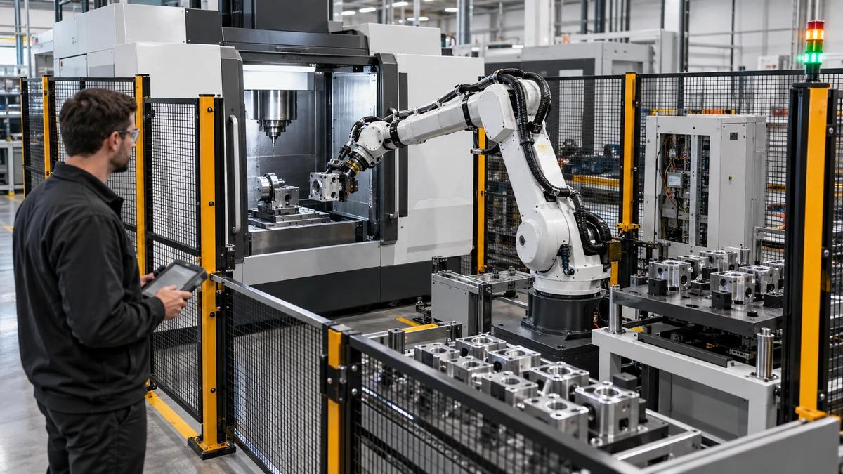
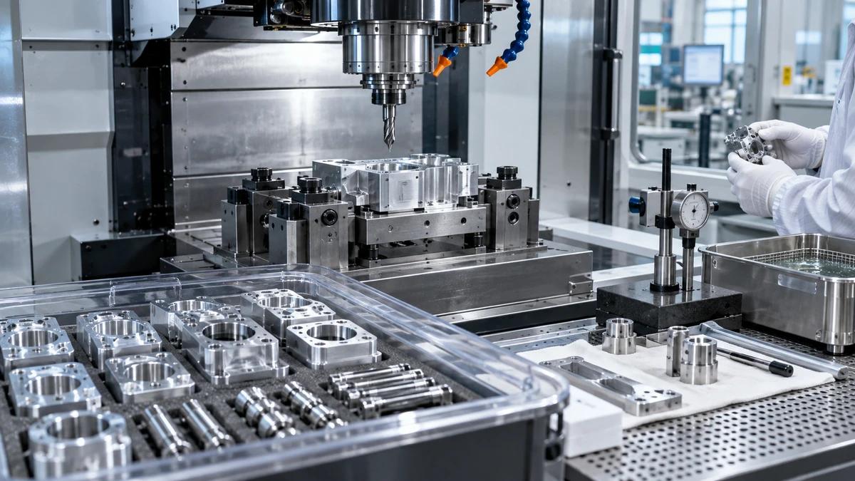
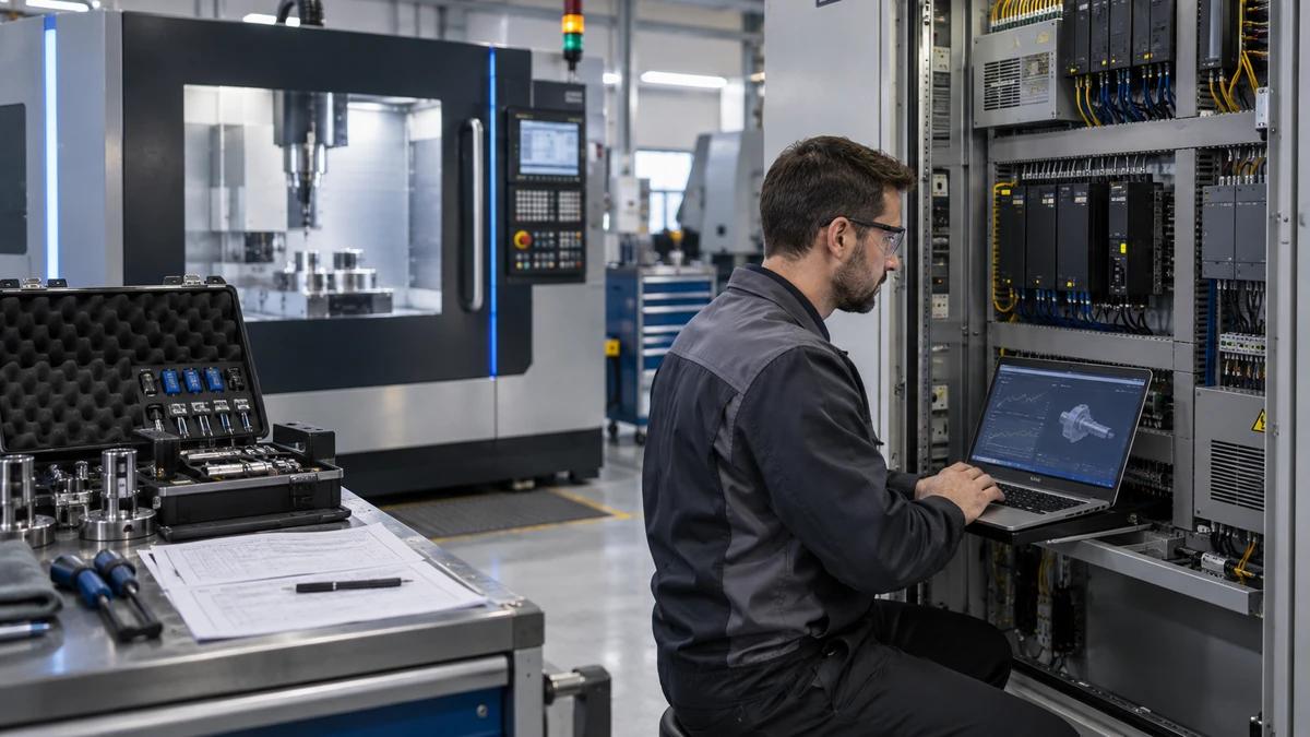
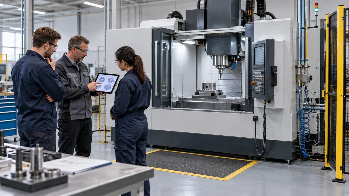
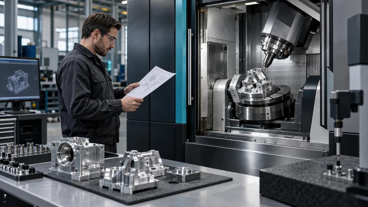
A CNC machining center for pump parts should be evaluated along the fluid path, because housing bores, sealing faces, impeller geometry, and mounting features work as one assembly. Zhihe CNC builds a fluid-path passport that connects each function to datums, setups, tools, inspection, and production evidence.
This route is useful for pump bodies, covers, bearing housings, impellers, wear components, and related families. It avoids promising one universal process: materials, castings, hydraulic design, balance needs, corrosion allowance, tolerances, and volumes can change the correct machine and fixture plan.
Issue a Passport at the Inlet
Index part number, revision, material, casting or billet route, heat or lot, stock map, pressure-related features, flow surfaces, datums, seals, bearings, mounting, threads, balance features, coating allowance, cleaning, traceability, and inspection. Mark supplied information separately from assumptions.
Zhihe CNC asks the buyer to identify the assembly relationships that matter most. A locally accurate bore can still fail its function when its axis, face, or location does not relate correctly to the mating component.
Follow Five Stations Along the Fluid Path
| Station | Machining concern | Release evidence |
|---|---|---|
| Inlet and flange | Face, pattern, connection | Datum and location report |
| Casing passage | Stock, access, chips | Process and visual record |
| Impeller zone | Clearance and geometry | Feature inspection |
| Seal and bearing | Axis and face relation | Controlled setup result |
| Discharge and mounting | Assembly alignment | Final relationship check |
The stations turn a mixed feature list into an assembly-led process plan.
Read Cast Stock Before Choosing the First Datum
Review foundry route, draft, parting lines, cores, gates, risers, stock allowance, distortion, hardness, inclusions, repair rules, surface condition, and lot variation. Sample critical areas instead of assuming the nominal CAD stock exists on every blank.
A CNC machining center for pump parts cannot create a stable route when the first location consumes uneven allowance or exposes a casting condition that the fixture and tool plan never considered.
Protect the Bore-Face-Seal Relationship
Define the functional datum sequence for bearing seats, shaft bores, seal faces, cover joints, mounting feet, and bolt patterns. Record which features remain in one clamping, which require transfer, and how the relationship is re-established and measured after transfer.
Give Impeller Work Its Own Branch
Separate open, semi-open, and closed geometry; material; blank route; blade access; hub; bore; key or drive feature; trimming; balance allowance; burr control; surface needs; and inspection. Confirm whether the proposed process includes the complete impeller or only defined preparatory and finishing operations.
Zhihe CNC recommends testing the smallest access, longest tool, thinnest section, and most chip-sensitive passage that belongs to the quoted scope.
Match Tools to Pump Feature Families
| Feature family | Tool-plan question | Typical risk |
|---|---|---|
| Large faces | How is flatness retained? | Heat or interrupted stock |
| Deep bores | How is alignment checked? | Reach and chip evacuation |
| Seal grooves | How is width and position controlled? | Tool wear or burrs |
| Threaded ports | How are depth and chips managed? | Breakage or contamination |
| Blade passages | How is access verified? | Collision or deflection |
Build the magazine map for the combined family, including probes and sister tools.
Route Chips Away From Internal Passages
Map gravity, cavity depth, cross holes, pockets, fixture ledges, coolant direction, through-tool supply, air where permitted, recutting, conveyor, filtration, tank cleaning, and final component cleanliness. Define safe manual cleanout and the evidence required before machining resumes.
For pump parts, trapped chips can affect tools, inspection, assembly cleanliness, and downstream flow passages. The machine trial should make evacuation visible through the full sequence.
Connect Inspection to Hydraulic Function
Define measurable characteristics and methods for axes, diameters, faces, seal features, wall or stock conditions, blade geometry where relevant, threads, mounting relationships, and surface requirements. Identify free-state versus restrained measurement, temperature, cleaning, instrument reach, alignment, sampling, and decision rules.
Do not convert hydraulic performance claims directly into machining guarantees. Machining evidence should show the controlled geometric and surface conditions assigned to the process.
Witness a Fluid-Path Acceptance Run
Freeze representative blanks, fixtures, tools, programs, controller state, coolant, thermal sequence, measurement, sample size, limits, exceptions, and retest. The ISO 10791 series reference provides machining-centre test context, while the production trial must include the buyer's difficult pump features and transfers.
Review first-piece setup, stable-cycle output, tool events, chip handling, inspection delay, and accepted quantity.
Keep Safety Around Rotation and Ejection
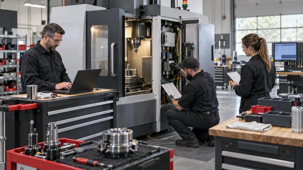
The ISO 16090-1 search reference offers safety context for machining centres. Responsible teams must assess workholding, casting condition, unbalance, tools, guarding, doors, interlocks, ejection, chips, coolant, loading, maintenance, cleanout, and recovery for the delivered setup.
No trial result justifies bypassing a protective function.
Run the Passport Through One Production Week
On day one, verify incoming stock and the first-location rule. On day two, compare bore and face relationships across repeated loadings. On day three, review tool wear, chip routes, coolant condition, and any passage cleaning. On day four, trace inspection queues and nonconformities. On day five, reconcile accepted output with planned capacity.
For every hold, preserve part identity, completed operations, stock state, fixture, tools, offsets, program position, measurements, and affected quantity. A restart needs an authorized route and a verification step.
Zhihe CNC recommends measuring total setup, handling, proving, cutting, tool events, cleaning, inspection, rework, scrap, maintenance, and recovery time. Gross cycle alone hides the constraints that determine shipment.
Close the week with one passport trace from blank certificate to released component. Any missing revision, datum, tool, inspection, or disposition link becomes an action with an owner and date.
Prove the CNC Machining Center for Pump Parts With an Assembly Pair
Select one stationary component and one rotating or alignment-related component that meet in the intended pump assembly. Freeze their revisions, materials, blanks, datums, fixtures, tools, programs, and inspection routes. The pair should expose a meaningful bore-face relationship, seal or bearing interface, mounting pattern, and the chip or access problem that most influences production.
Run the stationary part first and preserve its measured datum state. Then machine the mating component without quietly changing the interpretation of the assembly relationship. Use controlled identifiers so the buyer can connect each result to its actual blank, tool set, machine state, and measurement file. Document any feature completed by another operation or supplier instead of implying full-scope capability.
The CNC machining center for pump parts should also survive a normal production disturbance. Introduce a planned tool-life change, inspection hold, or repeat loading inside the approved test protocol. Observe how offsets, work identity, remaining stock, completed operations, and inspection status are preserved. The recovery part must be distinguishable from uninterrupted samples and released by the agreed evidence route.
Finally, assemble a digital relationship report. It should show what the machine trial demonstrated, what remains dependent on downstream finishing or assembly, and which hydraulic claims were not tested. Include total accepted-output time and the labor required for setup, chips, cleaning, inspection, and recovery. This creates a useful purchasing baseline without turning machining dimensions into unsupported pump-performance promises.
Document the final pair with photographs, tool assemblies, fixture revisions, program checksums, inspection files, accepted quantity, open assumptions, and named owners. That closeout lets a future team reproduce the CNC machining center for pump parts trial instead of relying on the memory of the demonstration crew.
Recognize the Limits of a Fluid-Path Trial
A trial cannot guarantee pump efficiency, pressure capability, corrosion life, balance, assembly performance, or output for every design and material. A CNC machining center for pump parts proves only the defined machining conditions and evidence. New castings, sizes, alloys, coatings, tolerances, fixtures, software, or sites require targeted revalidation.
FAQ
Why organize the process around the fluid path?
It connects machining features to assembly and functional relationships instead of isolated dimensions.
Which pump components belong in one review?
Include the housings, covers, bearing and seal parts, impellers, wear parts, and interfaces inside the quoted scope.
Why inspect casting stock early?
Uneven stock, distortion, hardness, and core conditions can change datums, tools, fixtures, cycle, and yield.
Should all bores be machined in one setup?
Not automatically; access, support, accuracy, inspection, and handling decide whether one or multiple controlled setups fit.
What makes an impeller trial representative?
It includes the relevant blank, geometry, access, tool reach, chip behavior, burr control, and inspection.
How should seal features be controlled?
Link their dimensions and surfaces to functional datums, tool condition, cleaning, and a reproducible measurement method.
Does the machine trial prove pump performance?
No. It proves defined machining results; pump performance also depends on design, materials, assembly, and operating conditions.
What time belongs in capacity planning?
Include setup, handling, cutting, tools, chips, cleaning, inspection, rework, scrap, maintenance, and recovery.
When should the passport reopen?
Reopen affected evidence after part, casting, material, fixture, tool, program, inspection, software, or site changes.
What should Zhihe CNC receive?
Send controlled CAD, drawings, blanks, materials, datums, critical features, volumes, inspection, and assembly relationships.
Build the Pump-Part Passport With Zhihe CNC
To evaluate a CNC machining center for pump parts, send Zhihe CNC your controlled housings, covers, impellers, materials, stock maps, datums, fixtures, tools, tolerances, surfaces, volumes, and inspection route. Review the milling machining center range, the product portfolio, and the contact route before issuing the passport.