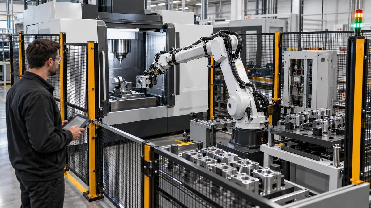
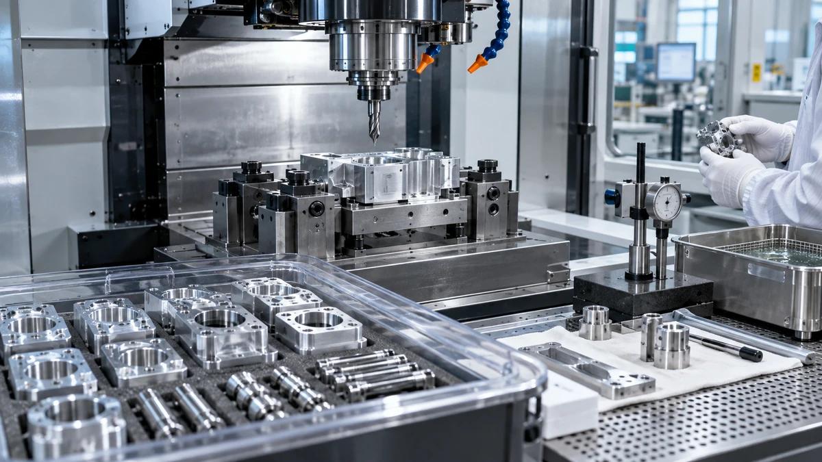
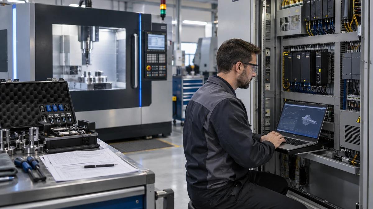
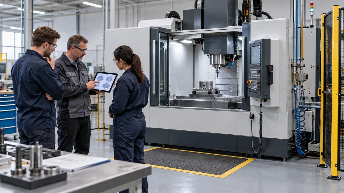
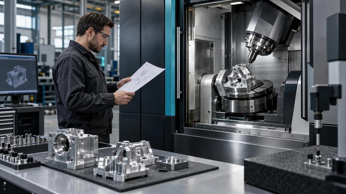
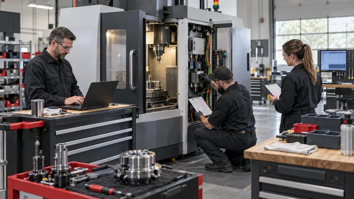
A CNC machining center for valve parts should be selected by tracing the pressure boundary through body bores, seat pockets, stem guides, bonnet joints, flanges, ports, and threads. Zhihe CNC uses that chain to reveal which datums, setups, tools, inspections, and records protect the intended assembly.
The method supports valve bodies, bonnets, covers, stems, discs, gates, and related components while respecting an important boundary: machining evidence does not by itself certify pressure performance or compliance. Those decisions remain with the responsible design, quality, testing, and regulatory owners.
Name Every Boundary Segment
Index part and revision, valve type, size, material, casting or forging route, heat or lot, stock allowance, flow bore, seats, stem axis, flange or end connections, bonnet joint, ports, wall-sensitive regions, sealing surfaces, threads, coating allowance, cleaning, marking, traceability, and inspection.
Zhihe CNC recommends tagging every assumption with an owner. A drawing without a defined stock state, datum interpretation, or measurement method is not ready to become an acceptance test.
Build the Boundary Evidence Chain
| Segment | Machining relationship | Evidence checkpoint |
|---|---|---|
| Flow bore | Axis and stock removal | Bore and alignment record |
| Seat pocket | Concentricity and face relation | Feature inspection |
| Stem guide | Axis to seat | Controlled relationship |
| Bonnet joint | Face and pattern | Flatness and location |
| End connection | Assembly orientation | Datum and thread report |
| Ports and drains | Intersection and cleanliness | Visual and dimensional release |
A break in the chain becomes a hold rather than an invisible assumption.
Interrogate the Blank Before Cutting
Review certificates, heat identity, foundry or forging route, draft, parting, cores, gates, risers, flash, scale, repair status, distortion, hardness, stock map, surface defects, and allowable disposition. Define how the blank is oriented and which feature establishes the first reliable location.
A CNC machining center for valve parts cannot recover material that is missing at a sealing or pressure-related feature. Stock verification belongs ahead of toolpath confidence.
Make Seat and Stem Axes Meet on Paper First
Translate functional relationships into a datum and setup diagram. Identify which axes and faces can remain in one clamping, which require repositioning, and how probing or inspection re-establishes the relationship. Include fixture contact, clamp force, distortion risk, free-state measurement, and accessibility.
Assign Tools by Boundary Risk
| Operation | Evidence needed | Loss to contain |
|---|---|---|
| Bore roughing | Stock and load state | Chatter or drift |
| Seat finishing | Tool condition and size | Seal-related deviation |
| Flange facing | Flatness and finish | Assembly leakage risk |
| Threading | Gauge method and depth | Connection failure |
| Cross-port work | Breakthrough and burr plan | Contamination or blockage |
Combined tool lists must include gauges, probes, sister tools, limits, and replacement rules.
Plan Intersections, Burrs, and Cleanliness
Map every cross hole, passage intersection, thread runout, internal shoulder, blind volume, and chip trap. Define cutting direction, tool condition, deburring access, inspection, flushing, drying, preservation, and cleanliness release. Do not rely on a final wash to remove a burr that the process cannot see.
Zhihe CNC asks the trial to expose the hardest internal intersection rather than presenting only accessible external features.
Control Sealing Faces as a System
Record datum, tool assembly, runout, path, insert condition, speed, feed, coolant, interruptions, surface requirement, flatness, temperature, cleaning, protection, and measurement. Preserve the face after machining so handling and inspection do not erase the evidence.
For seats or faces completed by downstream processes, state the machining allowance and handoff condition explicitly. Do not claim the result of an operation outside the proposed scope.
Run a Boundary Breach Drill
Select a controlled nonhazardous event such as a tool-life limit, probe deviation, uncertain stock area, burr finding, or measurement hold. Observe whether the team stops affected work, identifies parts, preserves tool and program state, records the evidence, assigns disposition, and authorizes recovery.
The drill does not involve pressure testing or deliberate damage. It tests the information path around the machining process.
Design a Representative Acceptance Lot
Freeze blank route, heat identity, fixture, tools, programs, controller state, coolant, thermal sequence, inspection, sample size, limits, exceptions, and retest. The ISO 10791 series reference supplies machining-centre test context. The buyer's protocol should include difficult axes, seat relationships, intersections, threads, chips, and repeated loading.
Reconcile accepted parts with traceable material and inspection records.
Keep Machine Safety Separate From Pressure Claims
The OSHA machine-guarding resource provides general guarding context. The delivered process still needs assessment of fixtures, irregular blanks, tools, access, doors, interlocks, ejection, chips, coolant, loading, maintenance, and cleanout under applicable local requirements.
Machining acceptance is not a substitute for the valve maker's pressure testing or product certification.
Audit the Chain From Heat Number to Released Part
Choose one accepted component and one held component. Trace each from material identity through blank receipt, revision, setup, program, tools, offsets, machine state, inspection, deburring, cleaning, nonconformance, disposition, marking, and downstream handoff. The records should agree with the physical items.
Measure setup, handling, proving, cutting, tool events, chip clearing, deburring, cleaning, inspection, rework, scrap, maintenance, and recovery. A short cutting cycle cannot compensate for a long invisible hold.
Zhihe CNC recommends trend charts by boundary segment. If seat results move while flange results remain stable, the team can investigate the relevant tools, datums, fixture contacts, heat sequence, and measurement method instead of adjusting the entire process.
After any drawing, material, blank, fixture, tool, program, software, inspection, supplier, or site change, identify which chain links reopen. Archive earlier approvals and the conditions that supported them.
Challenge the CNC Machining Center for Valve Parts With a Datum Swap
Choose a representative body or bonnet that requires at least two orientations. In the first orientation, establish the primary bore, seat, or joint reference. In the second, recover the defined relationship for the opposing connection, stem guide, bolt pattern, or port. Freeze the blank, fixture revisions, locators, clamp sequence, tools, probes, program, thermal state, and measurement plan before cutting.
Measure the relationship after the first setup and again after the transfer using the approved alignment method. Record contact cleanliness, locating evidence, clamp condition, probe qualification, offsets, and any manual correction. If an adjustment is allowed, state its limit and authorization. Do not tune several values until the result passes and then discard the path that produced it.
A CNC machining center for valve parts must preserve boundary evidence through exception handling. Hold one component after a safe planned trigger such as an uncertain burr, tool-life limit, or inspection disagreement. Identify the affected heat, part, operation, tools, stock state, and downstream quantity. Resume only after the responsible owner approves a recovery and verification route.
Close the challenge by reconciling feature results, deburring, cleaning, material identity, and disposition with the physical component. State which pressure-related claims remain outside machining acceptance. A successful datum swap proves a defined setup and evidence system under stated conditions; it does not authorize broader ratings, materials, sizes, or compliance claims without new review.
Archive the datum-swap file with blank identity, fixture condition, probe results, offset changes, feature reports, burr and cleaning evidence, disposition, and open limits. The record makes the CNC machining center for valve parts decision fully reviewable after staff, supplier, production, or schedule changes.
State the Boundary of the Machining Evidence
The method cannot guarantee leakage class, pressure rating, service life, corrosion behavior, or legal conformity. A CNC machining center for valve parts demonstrates defined geometric, surface, process, and traceability results under controlled conditions. The responsible manufacturer must connect those results to design, material, assembly, testing, and applicable requirements.
FAQ
Why use the pressure boundary as the organizing idea?
It connects body, seat, stem, joint, connection, and port features to the relationships the assembly depends on.
Does machining evidence certify a valve?
No. Certification and pressure performance also require responsible design, materials, assembly, testing, and compliance decisions.
Which blank records should be retained?
Keep material and heat identity, route, repair status, stock evidence, receiving checks, and disposition.
Why link seat and stem axes?
Their controlled relationship can affect assembly and sealing behavior, so setup and measurement should preserve it.
How should cross-hole burrs be handled?
Define access, cutting direction, deburring, inspection, flushing, and cleanliness release before production.
What belongs in a sealing-face record?
Include datum, tool, runout, path, condition, coolant, temperature, surface, flatness, cleaning, protection, and measurement.
What is a boundary breach drill?
It is a controlled information-flow test using a safe machining or quality hold, not a pressure event.
What makes an acceptance lot representative?
It uses controlled production-like blanks, setups, tools, heat, inspection, repetitions, and difficult boundary features.
When does the evidence chain reopen?
Reopen affected links after relevant part, material, stock, fixture, tool, program, inspection, supplier, software, or site changes.
What files should Zhihe CNC receive?
Send controlled CAD, drawings, blanks, materials, datums, boundary features, tolerances, volumes, and inspection plans.
Build the Valve Boundary File With Zhihe CNC
To evaluate a CNC machining center for valve parts, send Zhihe CNC your controlled bodies, bonnets, trim parts, materials, blank maps, datums, seat and stem relationships, tools, volumes, deburring, cleaning, and inspection needs. Review the machining center range, the company profile, and the project contact route before approving the chain.