

A CNC machining center probing system is valuable only when the measurement changes a defined decision. Before selecting hardware, map how a reference is established, which feature is measured, what the control may update, who owns the limit, how exceptions are contained, and which independent inspection still releases the part. Zhihe CNC can review probing interfaces as part of a machine configuration and application discussion. The buyer must provide the workpiece, fixture, datum strategy, control requirements, quality method, and local responsibilities. A probe does not make every setup correct, certify the product, or remove the need for a controlled measurement system. Follow One Offset From Birth to Retirement Choose one work offset on a representative part. Record who creates it, which probe routine touches which surface, what coordinate is calculated, whether an automatic update is permitted, where the value is stored, and which event retires it. This lifecycle reveals more than a list of probe features. An offset can be technically valid but operationally unsafe if no one knows which program wrote it. It can also be stale after a fixture change, crash, maintenance event, or part-family switch. Give every automated value an identity, source, timestamp or production context, allowed range, and reset rule appropriate to the control and process. Separate Four Measurement Jobs Do not put every probing activity into one bucket. Workpiece setup, in-process observation, tool setting, and final product inspection answer different questions. They may use different devices, routines, tolerances, environmental assumptions, and owners. Measurement job Typical decision What it does not prove by itself Owner to name Workpiece location Establish or verify datum and orientation Final part conformance Setup / process engineering Tool setting Establish length or diameter and detect defined events Tool life in every cut Tooling / production In-process probing Observe a feature or process state Independent product release Process / quality Post-process inspection Decide conformance under an approved method Machine cause for every deviation Quality Machine verification artifact Check a defined machine or setup condition Capability for all products Maintenance / metrology This distinction keeps a CNC machining center probing system from becoming a vague promise to "measure everything." Start With Datum Logic, Not Probe Travel Mark primary, secondary, and tertiary datum features on the controlled drawing and fixture plan. Show how the physical part is supported and clamped before the probe moves. Identify dirt, burrs, casting variation, stock allowance, flexible walls, and interrupted surfaces that can change the contact. Then define the probing path, approach, stylus orientation, protected moves, clearance, and failure behavior. A routine that reaches a feature in CAD may be unsuitable in the real fixture. Include clamps, tools, chips, coolant, doors, rotary positions, and operator access in the collision review. Decide What Automation May Change List each possible automatic action: set a work coordinate, update a tool offset, rotate a coordinate system, select a program branch, flag a part, stop the cycle, or call an operator. Give each action a permitted range and an exception route. If the result exceeds the range, the safest action may be to stop and investigate rather than apply a larger correction. Avoid cascading compensation. A probe update can hide a moving fixture, damaged tool, thermal change, chip under the part, or incorrect program. Store the original observation, the applied value, and the reason. The correction log should let quality and production reconstruct what happened to every affected piece. Design the Stylus Around the Feature Stylus ball, stem, length, orientation, joints, access, and expected contact direction affect the measurement chain. Use manufacturer guidance and a qualified application review. Long or complex assemblies may improve reach while adding collision, stiffness, calibration, or repeatability concerns. Create a stylus passport with component identity, assembly drawing, calibration state, permitted routines, storage, inspection, replacement, and damage rules. Do not silently rebuild the assembly from similar parts. If the geometry changes, review the affected calibration and routines. Renishaw's official machine-tool probe software reference shows that software and controller prerequisites vary. That is the procurement lesson: hardware, interface, control, macros, options, and training must be checked as one package. Give Calibration a Trigger and an Owner Calibration is not a ceremonial step performed once at installation. Define which artifact, method, environment, spindle or rotary state, and routine apply; who is authorized; where results are stored; and which events require review or recalibration. Triggers can include stylus replacement, collision, spindle work, software change, unusual result, or movement of relevant hardware. Keep each event with the CNC machining center probing system baseline so the next calibration review begins with a known physical and software state. Separate probe calibration from machine geometry verification and product measurement-system analysis. These records interact, but they are not interchangeable. When a result moves, a clear boundary helps the team investigate the correct layer. Build a Protected-Move Failure Table Walk through ordinary exceptions: missing part, part too high, wrong fixture, broken stylus, dirty surface, lost signal, low battery where applicable, program mismatch, unexpected contact, and out-of-range result. Define what the machine does, what message appears, what work is held, and who may restart. Do not create dangerous conditions just to test a response. Use supplier-approved methods, simulations, controlled artifacts, or safe staged checks under the site's procedures. A stopped cycle is only useful when the next person can identify the cause and the affected production. Compare Contact, Non-Contact, and Offline Routes The best route depends on the feature and decision. A contact probe may suit datum location or certain feature checks. A non-contact tool setter can observe defined tool conditions. Offline equipment may provide independent inspection with different uncertainty and environmental control. Many processes need a combination. Compare those routes inside the CNC machining center probing system plan, not as isolated hardware purchases. Route Useful question Integration work Boundary to state Spindle contact probe Where is the part or selected feature? Receiver/interface, macros, stylus, program, calibration Contact and access conditions Contact tool setter What is the defined tool length/diameter state? Mounting, protected moves, routines, cleaning Tool geometry and contact method Non-contact tool system Is a defined tool feature present or changed? Beam path, air/cleaning, software, environment Detectable geometry and contamination Offline inspection Does the part meet the approved release method? Transfer, alignment, gauge program, traceability Support, environment, uncertainty, sampling Renishaw's tool-setting technology explanation distinguishes contact and optical approaches and their control interfaces. The buyer should still validate the selected route for the real tools and site. Write the Program as a Quality Record Control probing macros, subprograms, variables, protected moves, feature definitions, update limits, alarms, and result storage by revision. Tie the released routine to the machine, control, interface, stylus, fixture, part revision, and program. Back up files and prove that they can be restored. Restrict editing according to the buyer's governance. A small change to a variable or coordinate can alter the decision while leaving the program name unchanged. Use change requests that state the reason, affected parts and features, verification, approver, and effective date. Test Repeatability Without Confusing It With Accuracy Repeated readings under stable conditions can show consistency for the tested setup. They do not prove truth against a traceable reference or guarantee every workpiece measurement. Design checks that separate repeatability, bias, machine state, stylus behavior, fixture variation, and product variation. ISO lists ISO 230-10 within its machine-tool test-code family for determining measuring performance of probing systems on numerically controlled machine tools. Use the applicable standard, supplier method, and metrology expertise when required; this article neither reproduces the standard nor declares compliance. Run a Two-Part Acceptance Exercise Part A should verify integration: hardware identity, interface, signal, programs, protected motion, calibration, data, alarms, backup, and permissions. Part B should follow a representative workpiece from loading through probing, machining, exception handling, independent inspection, and release. Include a normal part and a controlled boundary condition. Record raw observations, updates, timestamps, program revisions, measurement alignment, held-work decisions, and responsible roles. The CNC machining center probing system passes only the claims agreed in the test plan. Count the Minutes the Probe Adds and Removes Compare complete routes. Count manual finding, part alignment, tool setting, probing, calibration, cleaning, program time, exception response, independent inspection, offset review, and rework. Use accepted parts as the denominator. A shorter machine cycle can still create a longer release route if exceptions wait for engineering. Do not publish universal savings. Volume, mix, staffing, fixture consistency, gauge queues, and current setup method change the result. Keep the baseline and the proposed route under the same scope. Keep Product Release Independent Where Required Machine probing can support process control, but the buyer's drawing, contract, quality plan, regulatory obligations, and approved measurement system determine product release. State which features are monitored in the machine and which require independent inspection. If probe data feeds a quality system, define data identity, units, coordinate alignment, storage, retention, access, and treatment of missing or suspect records. A dashboard is not traceability unless its source and decision rules are controlled. Ten Questions About a CNC Machining Center Probing System Does a spindle probe replace final inspection? Not automatically. It measures defined features in the machine environment; product release follows the approved quality method and applicable obligations. Can the probe update offsets automatically? It can when the selected control, software, program, and process are designed for it. Define permitted ranges, records, stop rules, and authority. What happens when a reading is far outside the limit? Use a controlled exception path: stop where appropriate, preserve the observation, contain affected work, investigate the cause, and require authorized restart. Is probe repeatability the same as measurement accuracy? No. Repeatability describes consistency under stated conditions; accuracy and uncertainty require suitable references, methods, and analysis. How should a stylus be selected? Match the real feature, access, contact direction, length, stiffness, environment, and supplier limits, then validate the complete assembly. When should calibration be reviewed? After defined triggers such as stylus change, collision, movement, spindle service, software change, unusual readings, or scheduled control points. Can a probe detect a dirty fixture? It may reveal an unexpected location, but the result does not identify every cause. Cleaning, fixture checks, and investigation rules remain necessary. What software belongs in the quotation? Confirm controller compatibility, interface, required options, macro packages, protected moves, reporting, licenses, backups, and training. How should probing time be justified? Compare the entire accepted-part route, including setup, measurement, exceptions, inspection, holds, and rework under the same production mix. Which application files help Zhihe CNC review probing? Send drawings, datums, fixture concept, tool list, target routines, control preference, quality plan, data needs, exceptions, volumes, and service location. Turn the Offset Map Into a Zhihe CNC Review Explore the Zhihe CNC machining-center range, read the company profile, and send the controlled application pack through the contact page. Request a dated machine and control configuration, probing hardware and software scope, interface responsibility, stylus and calibration plan, trial routines, training, backup, acceptance boundary, and service owner. A strong CNC machining center probing system is not defined by how many cycles contain a probe move. It is defined by whether each observation leads to a clear, traceable decision.
Who Owns the Offset? A CNC Machining Center Probing System Plan
- Machine Selection Guide
Posted by Zhihe CNC On Sep 10, 2026
Featured Blogs
Tag:
Share On
Featured Blogs
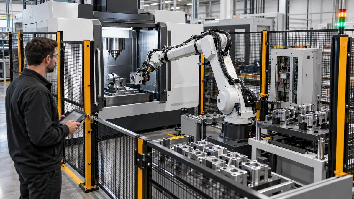
Custom CNC Automation Solution: Write the Interface Contract Before the Robot Arrives
Design a custom CNC automation solution around explicit machine, robot, fixture, safety, data, recovery, and changeover interfaces before integration.
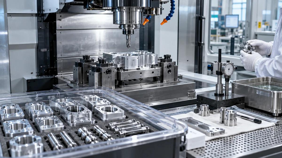
CNC Machine for Lithium Battery Equipment Parts: Control Contamination and Interfaces Together
Select a CNC machine for lithium battery equipment parts by linking datum control, contamination prevention, fixture design, cleaning, inspection, and traceability.
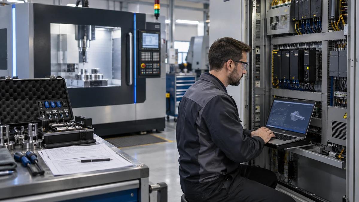
CNC Machine After Sales Service: Build a Severity-Based Recovery Playbook
Evaluate CNC machine after sales service through a severity-based playbook covering intake, triage, escalation, spare parts, remote support, and closure evidence.
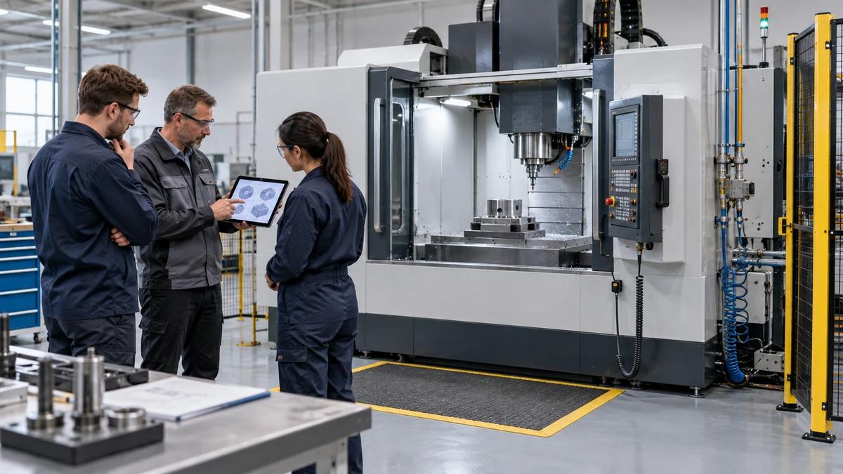
CNC Machine Installation and Training: Design the Handover Around the First Independent Shift
Build a CNC machine installation and training handover around site readiness, commissioning evidence, role-based competence, recovery paths, and supervised production.
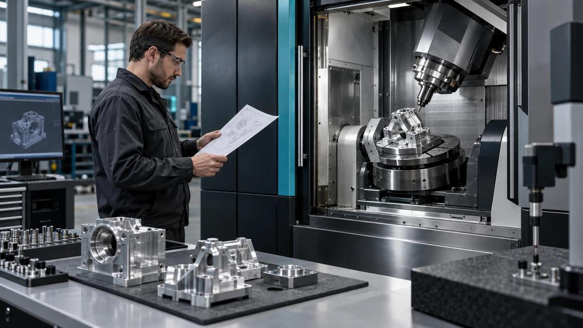
CNC Machining Center Quotation: Normalize the Scope Before Comparing Prices
Turn a CNC machining center quotation into a decision-ready scope by normalizing configuration, acceptance, delivery, training, warranty, and ownership assumptions.
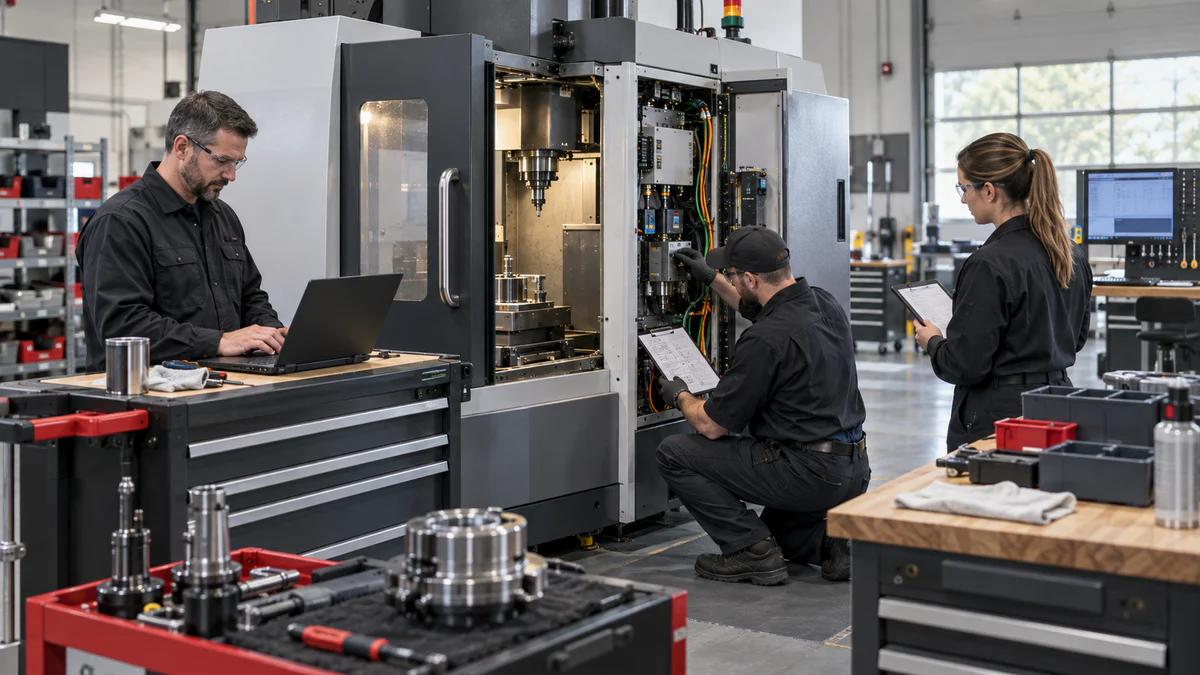
Before Territory Launch: A CNC Machining Center Distributor Service Drill
Test a CNC machining center distributor before territory launch with practical service drills for intake, escalation, spare parts, field work, and response quality.