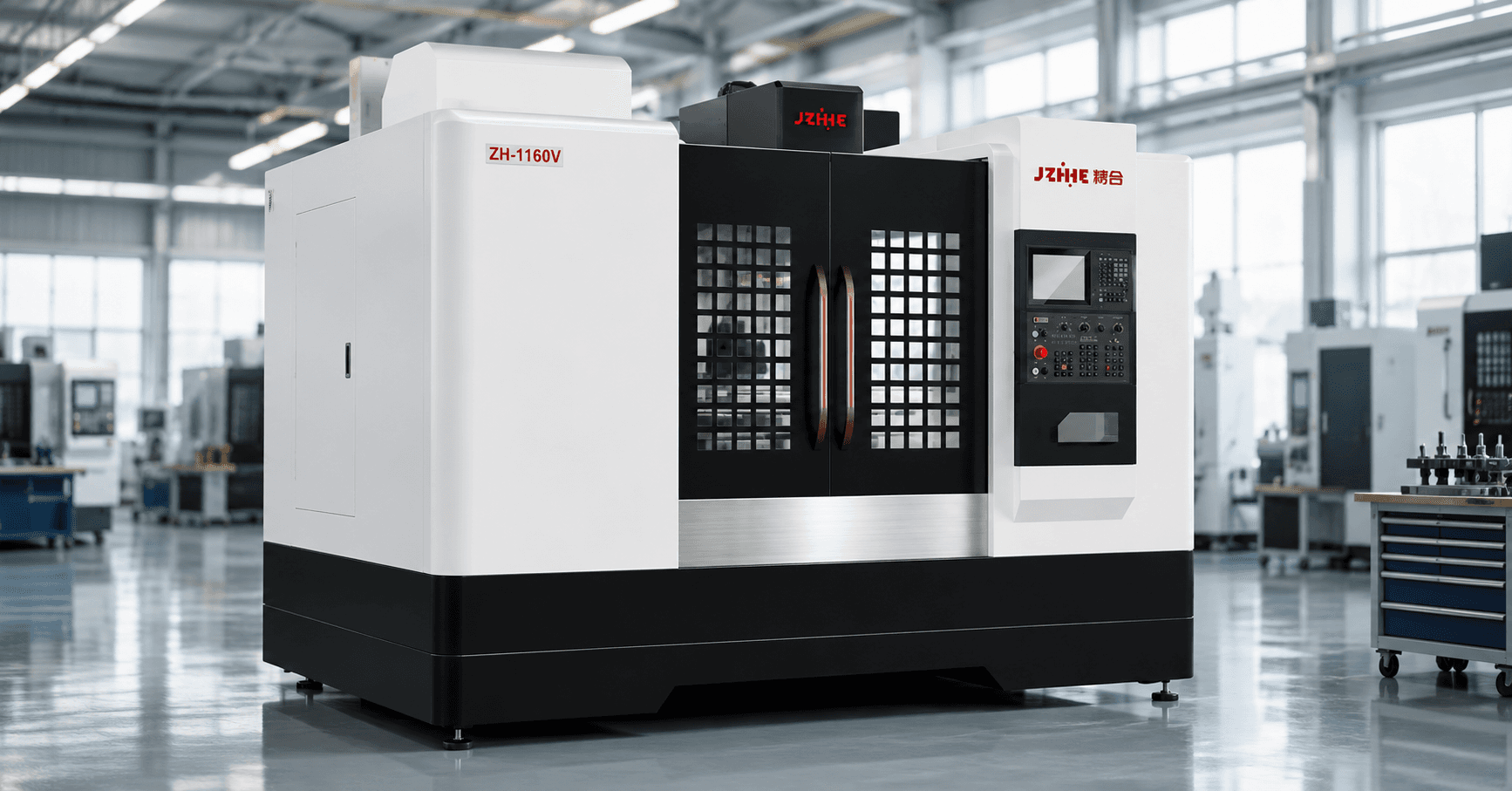
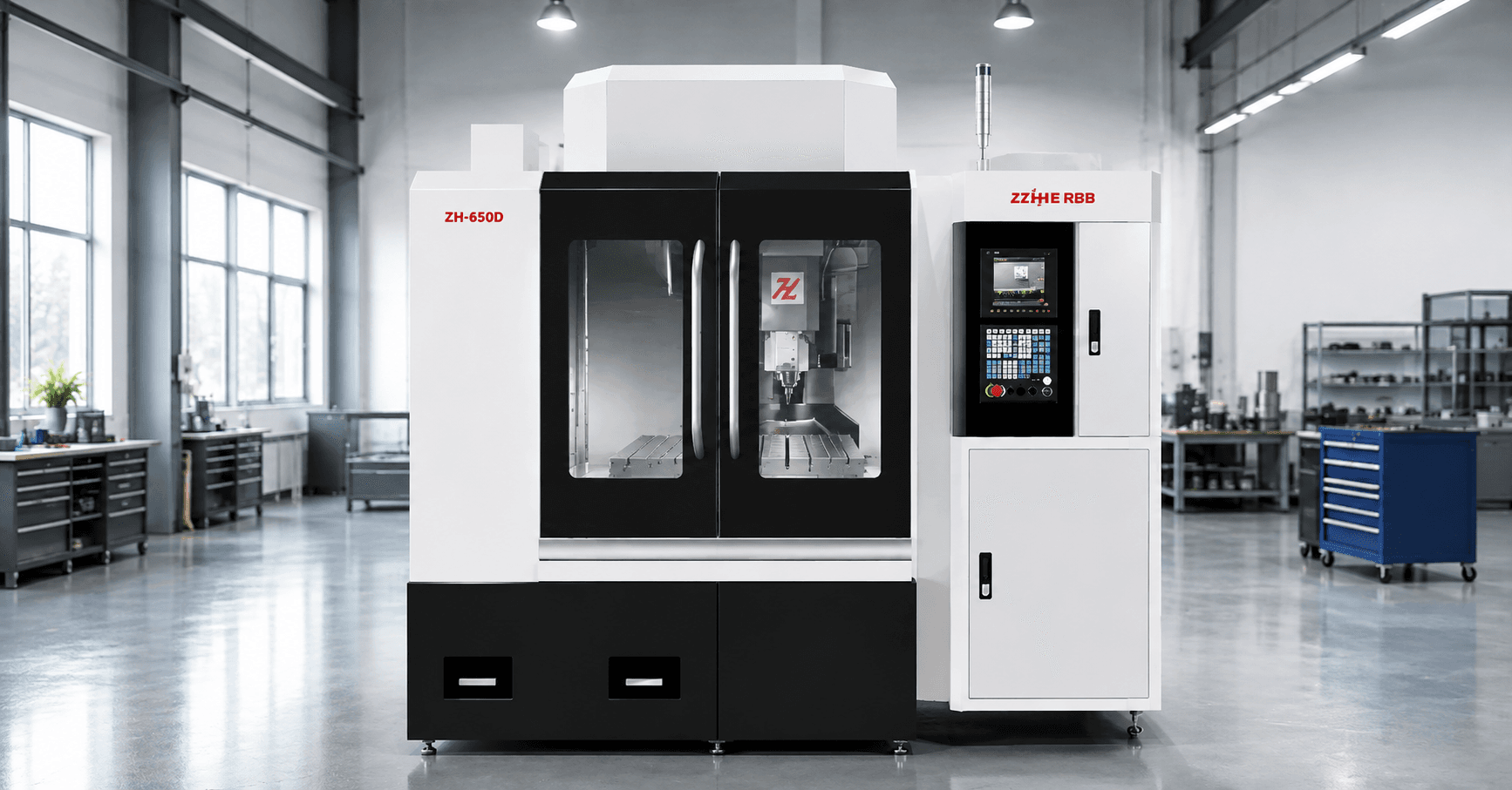
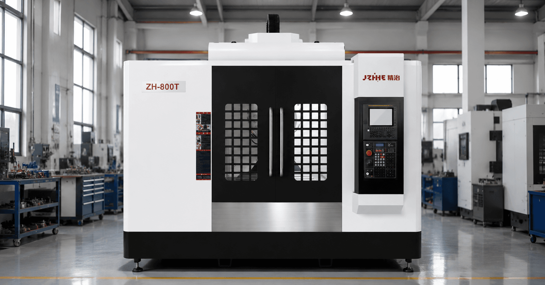
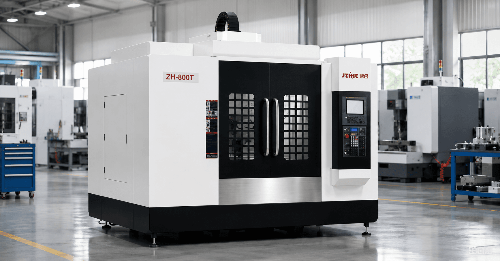
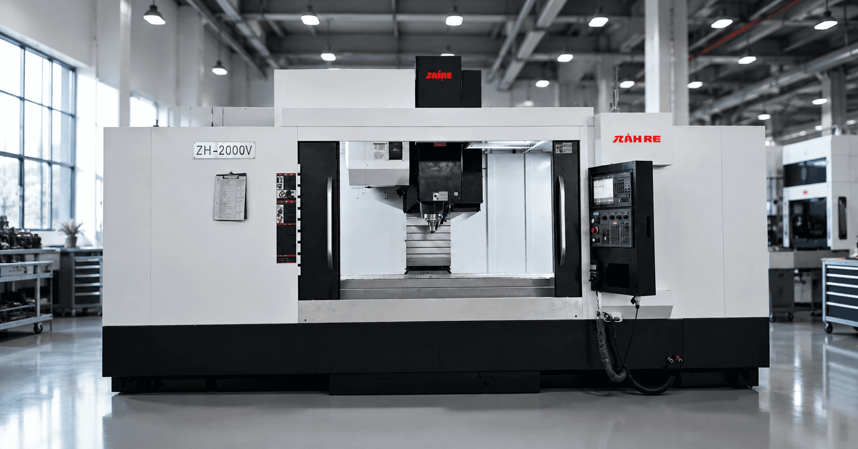
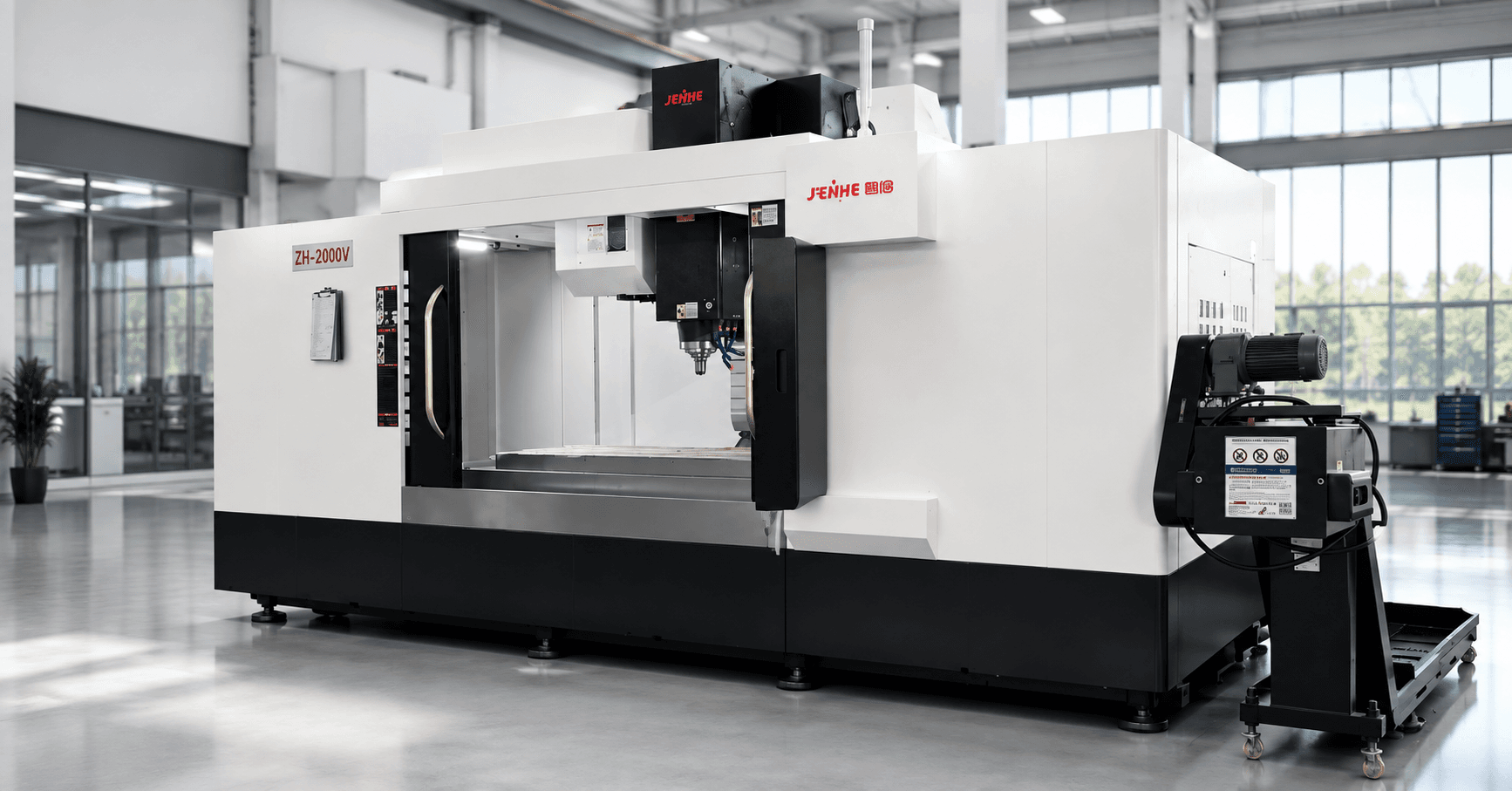
A CNC milling machine for metal parts should be selected from a material behavior matrix that connects cutting force, heat, chip form, tool wear, wall stability, finish, coolant, and cleaning to the actual part family. The label metal parts is too broad to support a reliable spindle, fixture, tooling, or cycle decision.
The matrix makes differences visible before the buyer compares machines. Aluminum may be limited by chip volume and built-up edge, steel by torque and tool load, stainless steel by work hardening, cast iron by dust and abrasion, and copper alloys by burrs or surface requirements.
Start With Material State, Not Only Material Name
Record specification, grade, hardness, heat treatment, stock form, coating, surface condition, and lot variation. A forged blank, casting, extrusion, flame-cut plate, and pre-machined block can behave differently even when their nominal chemistry is similar.
Add blank allowance, residual stress, scale, inclusions, interrupted cuts, and supplier variation. Identify which conditions are contract-controlled and which the machining process must absorb.
Matrix Cell A: Aluminum and High Chip Volume
Map spindle speed, acceleration, flute space, chip evacuation, coolant or lubrication, enclosure wash, conveyor capacity, fixture drainage, and cleaning. High removal rates can shift the bottleneck from cutting to chips, washing, or part handling.
Check built-up edge, burrs, thin-wall movement, cosmetic surfaces, and hollow sections that retain chips. Include tool-life and surface evidence across a full batch, not only a short new-tool sample.
Matrix Cell B: Carbon and Alloy Steel
Define cutter diameter, engagement, roughing duration, drilling sizes, boring, tool reach, material hardness, and expected spindle load. Review torque and rigidity in the real speed range rather than comparing only maximum spindle speed.
Measure tool wear, heat, vibration, chip form, and finish. Plan coolant filtration and chip handling for the actual steel mix. Long heavy cuts can reveal thermal and structural behavior that a small demonstration part does not.
Matrix Cell C: Stainless Steel
Control rubbing, work hardening, heat, tool entry, dwell, recutting, and tool replacement. Use stable engagement and sharp tools. Record how pilot holes, tapping, deep features, and long tools change the window.
Define the response to a stopped cut or worn tool because restarting in a work-hardened region can create a different load condition. Track burr removal and surface contamination where downstream processes are sensitive.
| Material behavior | Machine/process focus | Evidence |
|---|---|---|
| High chip volume | Speed, evacuation, filtration, cleaning | Accepted output over a full batch |
| High cutting force | Torque, rigidity, holder, fixture | Load, vibration, dimensional trend |
| Work hardening | Stable engagement, sharp edge, no dwell | Tool condition and restart rule |
| Abrasive dust | Protection, extraction, way and coolant care | Maintenance and contamination checks |
| Thin-wall movement | Support, clamp force, balanced removal | Free-state inspection |
Matrix Cell D: Cast Iron and Abrasive Contamination
Review dry or wet strategy, dust and mist control, enclosure sealing, way protection, filtration, chip or sludge removal, and maintenance. Graphite and abrasive particles can affect coolant systems, sensors, surfaces, and nearby equipment.
Include interrupted cuts, casting skin, porosity, and local hardness. A CNC milling machine for metal parts must be configured for the contamination environment as well as cutting performance.
Matrix Cell E: Copper and Nonferrous Alloys
Define conductivity, ductility, burr sensitivity, surface finish, tool geometry, lubrication, and chip handling. Some copper alloys machine freely while others smear or form difficult burrs. Keep alloy identity and condition traceable.
Protect finished surfaces from chips and handling marks. If electrical or thermal function depends on the surface, define cleaning, oxidation, coating, and inspection requirements separately from appearance.
Add Feature Behavior to the Matrix
Materials do not act alone. Add thin walls, deep pockets, long bores, interrupted cuts, small threads, sealing faces, tight corners, and cosmetic areas. For each material-feature cell, record the weakest tool, fixture risk, chip trap, inspection method, and acceptance limit.
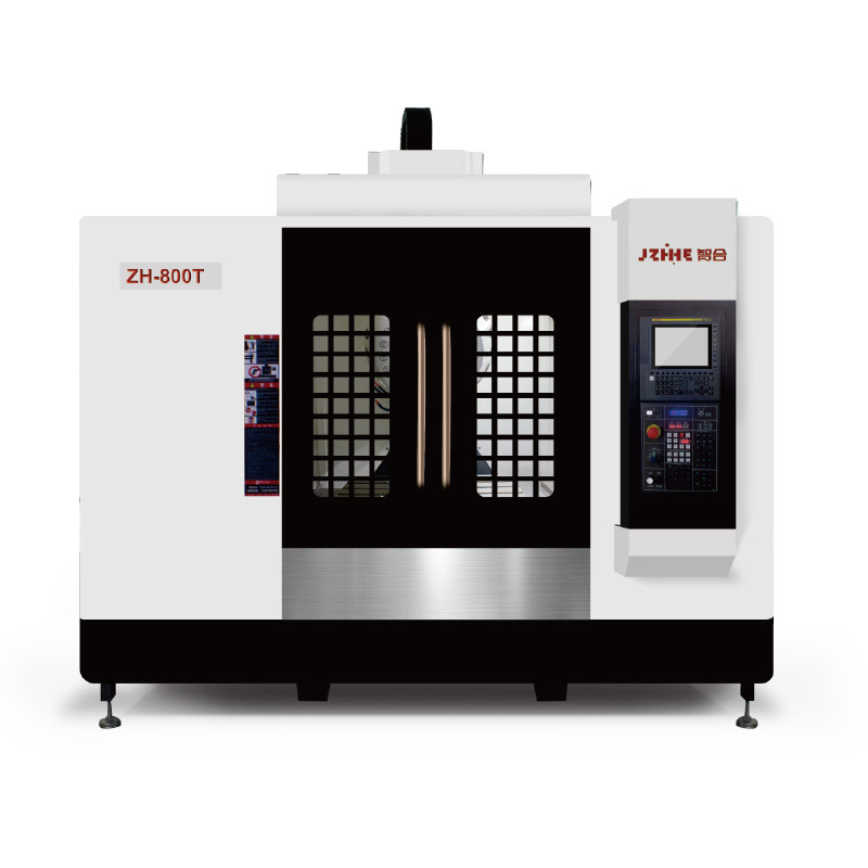
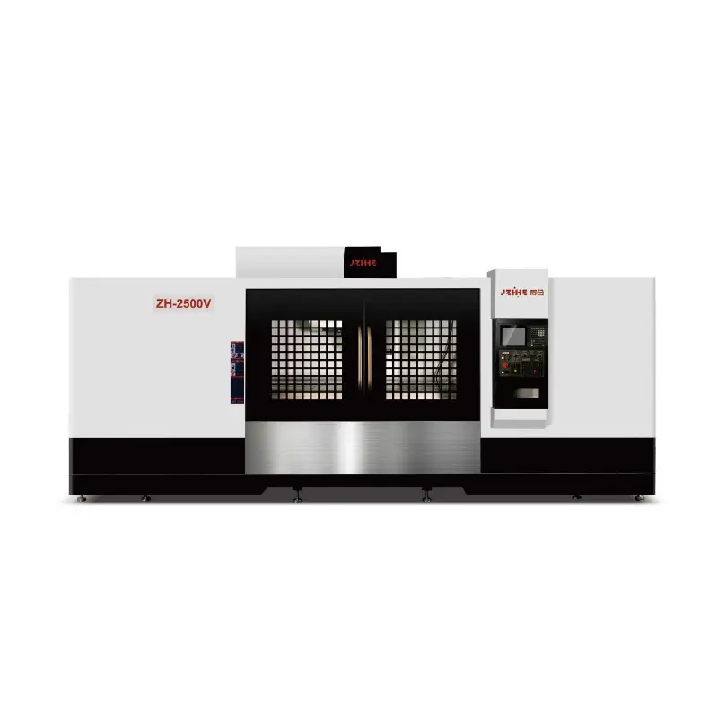
Review the milling machining center range as an architecture reference and compare it with the actual material-feature matrix.
Create Mixed-Production Change Rules
When one machine processes several materials, define program, tool, coolant, filter, chip bin, cleaning, inspection, and contamination changes. Measure changeover from last accepted part to first accepted part. Avoid mixing chips or fluids where recycling, quality, or downstream requirements prohibit it.
- Approve the material and blank identity before setup.
- Load the controlled program, tools, fixture, coolant, and inspection plan.
- Clean chips and contact surfaces to the required standard.
- Run the first-off part and verify material-specific risks.
- Record tool-life and maintenance effects by material family.
Use a Worst-Cell Trial
Select the matrix cell with the highest combined force, heat, reach, chip, wall, finish, or tool-life risk. Run it with production-like material and batch duration. Then verify an easy cell to confirm that the configuration does not create unnecessary cost or slow changeover for the rest of the mix.
Limits of a Material Matrix
The matrix organizes risk but does not replace cutting trials, material certificates, machine specifications, fixture engineering, or metrology. Not every shop should combine all materials on one machine. Separate equipment may be better when contamination, volume, tooling, coolant, or maintenance conflicts are large.
FAQ
Can one cutting-data table cover all steels?
No. Grade, hardness, stock condition, tool, engagement, coolant, and feature geometry change the stable window.
Why include cleaning in machine selection?
Chips, sludge, dust, and cross-contamination affect output, quality, recycling, maintenance, and downstream operations.
What is a worst-cell trial?
It tests the material-feature combination with the highest meaningful production risk instead of using an easy average part.
Should thin-wall parts be inspected while clamped?
In-process checks can help, but final functional acceptance may require free-state measurement after unclamping.
Submit a Material-Behavior Matrix
To evaluate a CNC milling machine for metal parts, send representative drawings, material grades and hardness, blank processes, batch sizes, annual mix, longest tools, heaviest cuts, thinnest walls, finish targets, chip and cleaning requirements, coolant rules, tool-life data, and inspection methods. Use the contact page to request a configuration review, and check Zhihe CNC's manufacturing background when assigning process responsibilities.