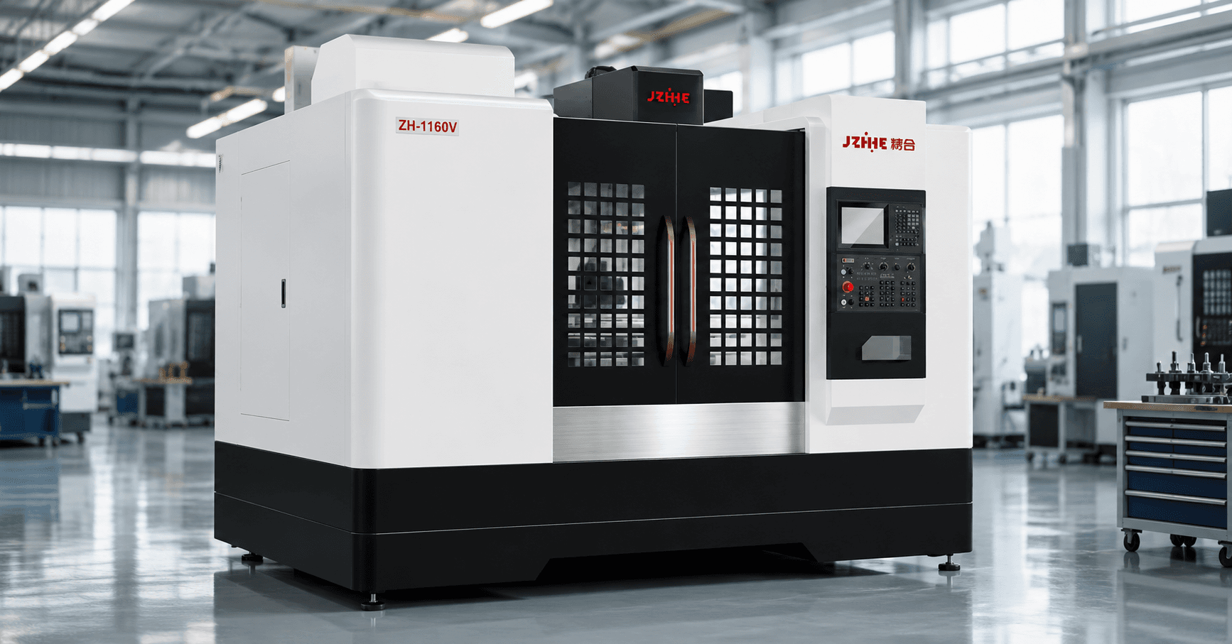
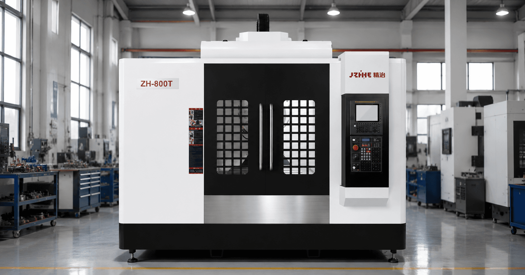
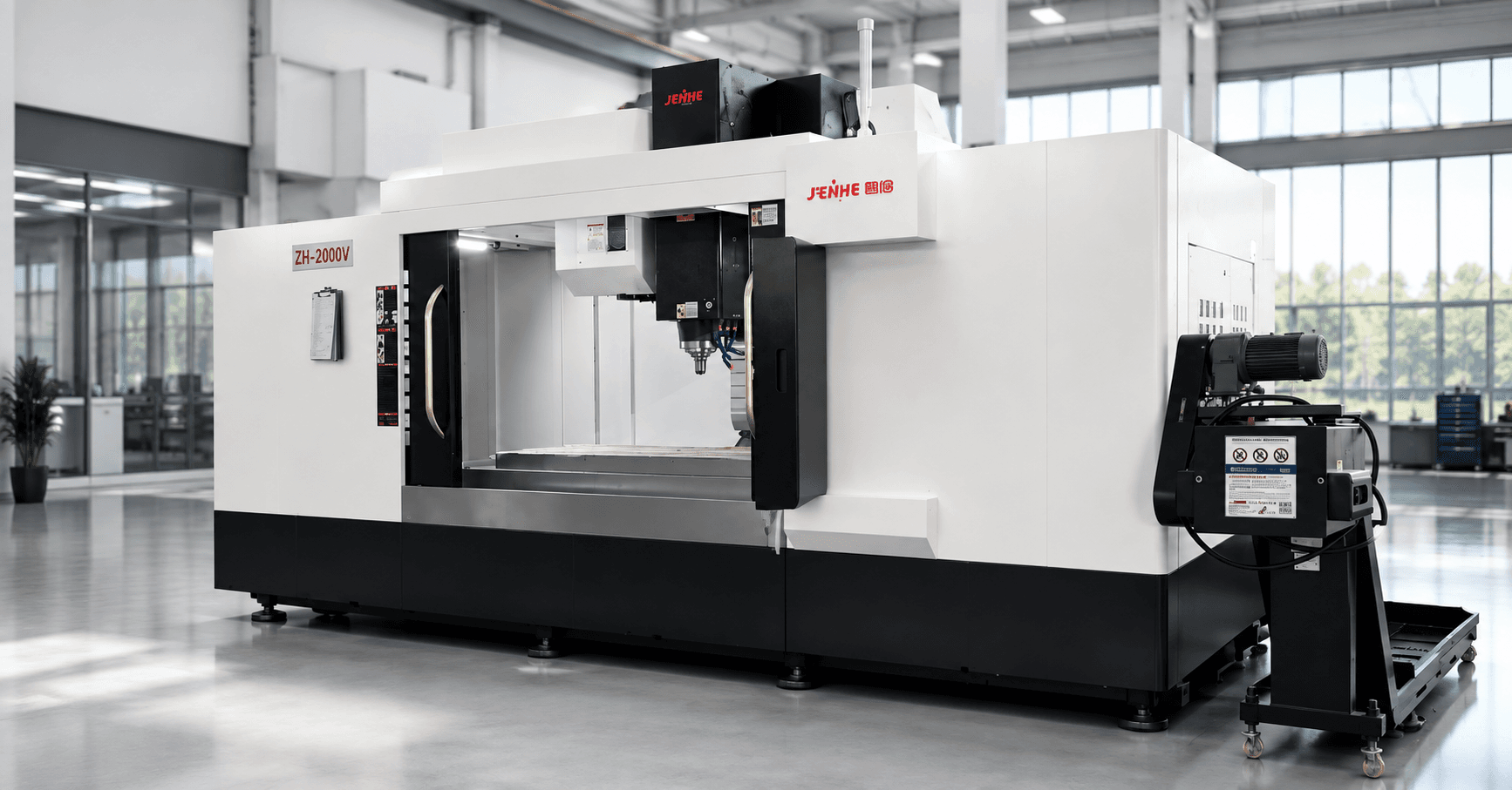
A double column machining center should be selected from a span-load envelope that combines mounted workpiece geometry, support reactions, bridge clearance, spindle reach, cutting vectors, thermal paths, chips, and released-part inspection. Travel numbers and table load are only the outside boundary.
The envelope makes structural decisions visible. It shows where the machine operates comfortably, where special fixtures or tools are required, and where a different architecture may reduce risk.
Draw the Mounted Workpiece Footprint
Model the blank, finished part, fixture, subplates, clamps, supports, lifting points, probes, tool holders, and inspection access. Mark doors, guarding, table edges, columns, crossrail, spindle nose, and maintenance zones.
Use the worst operation, not only the loading position. A part can enter the machine and still lose access near a column, at high Z, or with a long holder.
Map Support Reactions Before Table Load
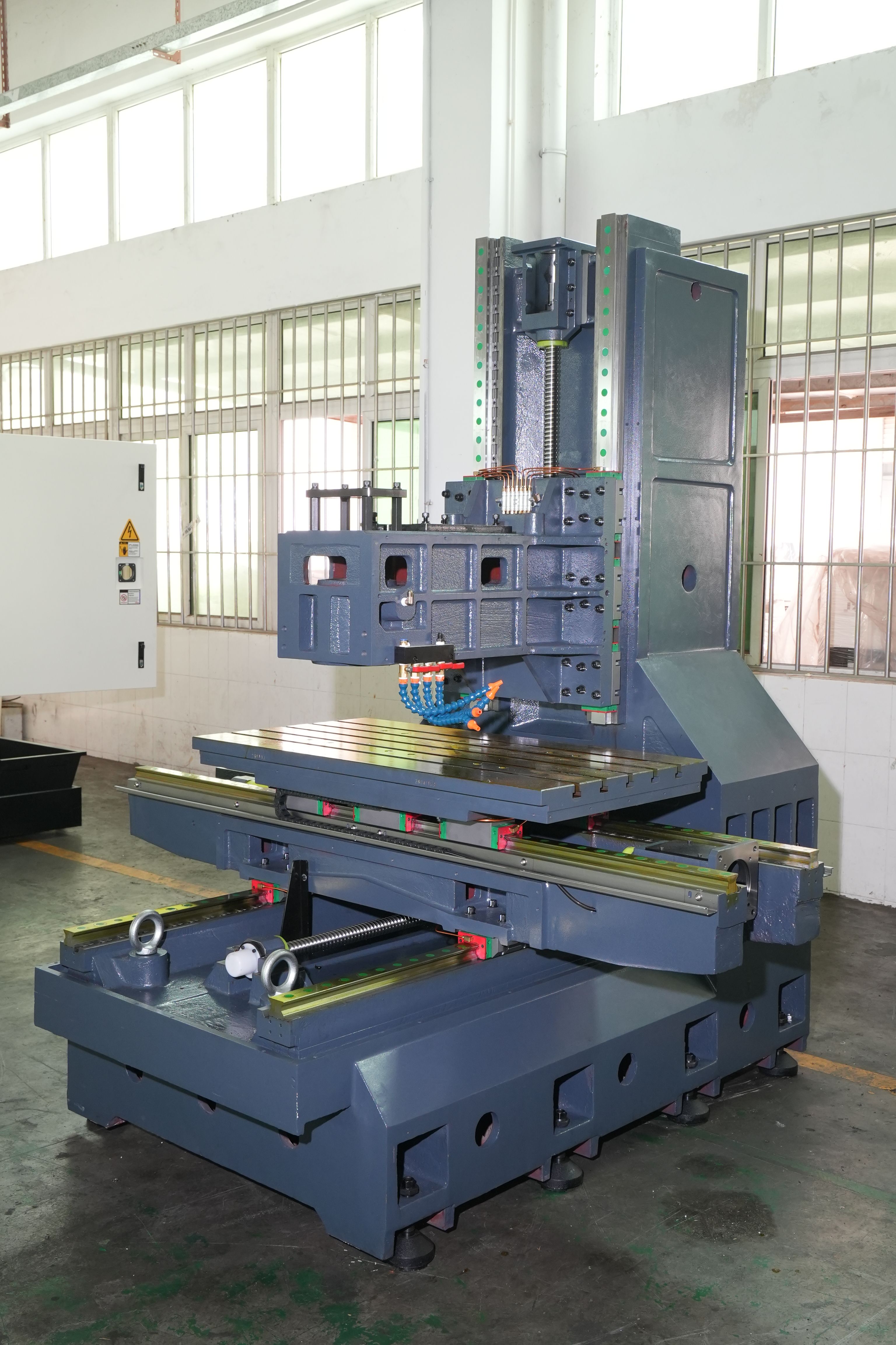
Calculate total mass, center of gravity, support locations, contact area, overhangs, clamp forces, local pressure, and lifting sequence. Distinguish distributed load from concentrated reactions.
A table-load rating does not describe local deformation in the part, fixture, support, or table. Use a support reaction map to plan leveling points and prevent distortion during clamping and cutting.
Measure the Working Span
Record distance between columns, table width, crossrail clearance, spindle-to-table range, ram extension, tool length, holder diameter, clamp height, and chip accumulation. Check every required X position.
The nominal bridge span can be reduced by covers, guards, attachments, or tool geometry. Keep a bridge-clearance exception sheet for features that need alternative orientation or tooling.
Route Cutting Vectors Through the Structure
For roughing, finishing, drilling, boring, and tapping, identify force direction, cutter engagement, spindle extension, axis position, material, and duty. Relate the load path to the work support and machine structure.
When comparing a double column machining center, rigidity should be discussed for the intended position and operation. General statements about heavy construction are not enough.
| Envelope layer | Required input | Decision output |
|---|---|---|
| Work and fixture | Mass, footprint, supports, clamps | Table and setup plan |
| Bridge clearance | Columns, crossrail, ram, holders | Reach and exception list |
| Cutting load | Tools, material, vectors, duty | Spindle and process window |
| Thermal path | Warm-up, coolant, room, cycle | Condition and compensation plan |
| Released geometry | Unclamped inspection condition | True process capability |
Separate Spindle Reach From Stable Reach
List short and long tools, extensions, angular heads if applicable, gauge lengths, cutter diameters, and feature depths. Model interference and required ram extension for each operation.
The tool may physically reach while stability, chip evacuation, finish, or measurement becomes unacceptable. Define a preferred reach band and an exception approval process.
Build the Thermal Path
Trace spindle heat, axis motion, coolant, cutting load, room temperature, sunlight, doors, foundations, workpiece temperature, warm-up, pauses, and measurement timing. State the expected production duty.
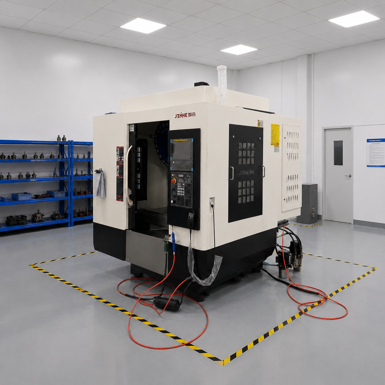
Review the gantry machining center range for platform context, then agree on conditioned trials. Thermal behavior should be evaluated as a system, not a single compensation value.
Give Chips an Escape Route
Estimate chip volume and direction by material and operation. Review enclosures, wash-down, conveyors, augers, tanks, filtration, access, cleaning, and the effect of large fixtures on flow.
Large workpieces can create pockets that retain chips and coolant. Include cleaning time and recutting risk in cycle and quality calculations.
Inspect the Part in Its Released State
Define machine checks, in-process probing, final inspection, support condition, clamp release sequence, temperature, time delay, instruments, datums, and uncertainty. Measure features that reveal twist, bow, squareness, and cross-feature relationships.
A part can pass while constrained and move after unloading. The acceptance plan should distinguish machine capability, fixture influence, and workpiece behavior.
Run the Three-Position Proof
- Select demanding features near the left, center, and right working zones.
- Use representative supports, tools, spindle extension, and cutting duty.
- Record geometry and thermal conditions before and after the run.
- Inspect the part clamped and released where movement matters.
- Review chips, access, cleaning, and operator recovery.
- Close bridge-clearance and support exceptions before purchase.
When a Large VMC Can Be Better
A large vertical machine may be more economical when the part and fixture fit comfortably, bridge span is unnecessary, loading is simple, and cutting duty is moderate. Double-column architecture is not automatically superior.
It becomes more compelling as width, mass, long-axis stability, heavy support, or multi-zone access increases. Use the span-load envelope to show why.
FAQ
Is double-column the same as gantry?
The terms often overlap, but layouts, moving elements, crossrail designs, and product naming vary. Confirm the actual architecture.
Does table load include fixtures?
Yes, the total mounted mass normally includes the workpiece, fixtures, subplates, clamps, and accessories, subject to the supplier definition.
Why check local support reactions?
Concentrated supports can deform the part, fixture, or table even when total mass remains below the published limit.
Should the trial part span the table?
Use a representative artifact or workpiece that exercises the required zones, reach, duty, and feature relationships.
Request a Span-Load Assessment
To configure a double column machining center, send blank and finished models, mass, center of gravity, support and clamp plan, lifting method, materials, tools, operations, tolerances, thermal duty, chip volume, inspection, destination, and site constraints. Use the contact page for an engineering review and consult the large-part coordinate-zone guide for setup planning.