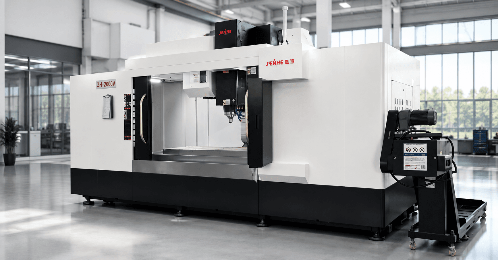
A gantry CNC machine for large flanges should be selected and programmed from a clock-face control plan that connects the datum circle, sealing face, center bore, bolt pattern, supports, thermal sequence, and released-part inspection. Overall diameter alone does not define the application because fixtures, clamps, probe access, tool reach, lifting, and distortion consume the usable envelope.
The clock-face method divides the mounted flange into repeatable zones. It helps the production team track where error, support, chips, heat, and inspection results occur instead of treating one large circular part as a single undifferentiated surface.
Define the Master Datum Circle
Identify the functional reference used by the mating assembly. It may be a pilot bore, outside diameter, register, face, or a defined combination. Record roundness, concentricity, runout, face relationship, and inspection condition. Separate the functional datum from a convenient rough blank reference.
Survey the incoming blank for diameter, thickness, bow, taper, stock distribution, casting or forging variation, and lifting features. Decide how much variation the fixture and probing routine must absorb. Do not center the process on an uncontrolled rough edge when the finished assembly uses another reference.
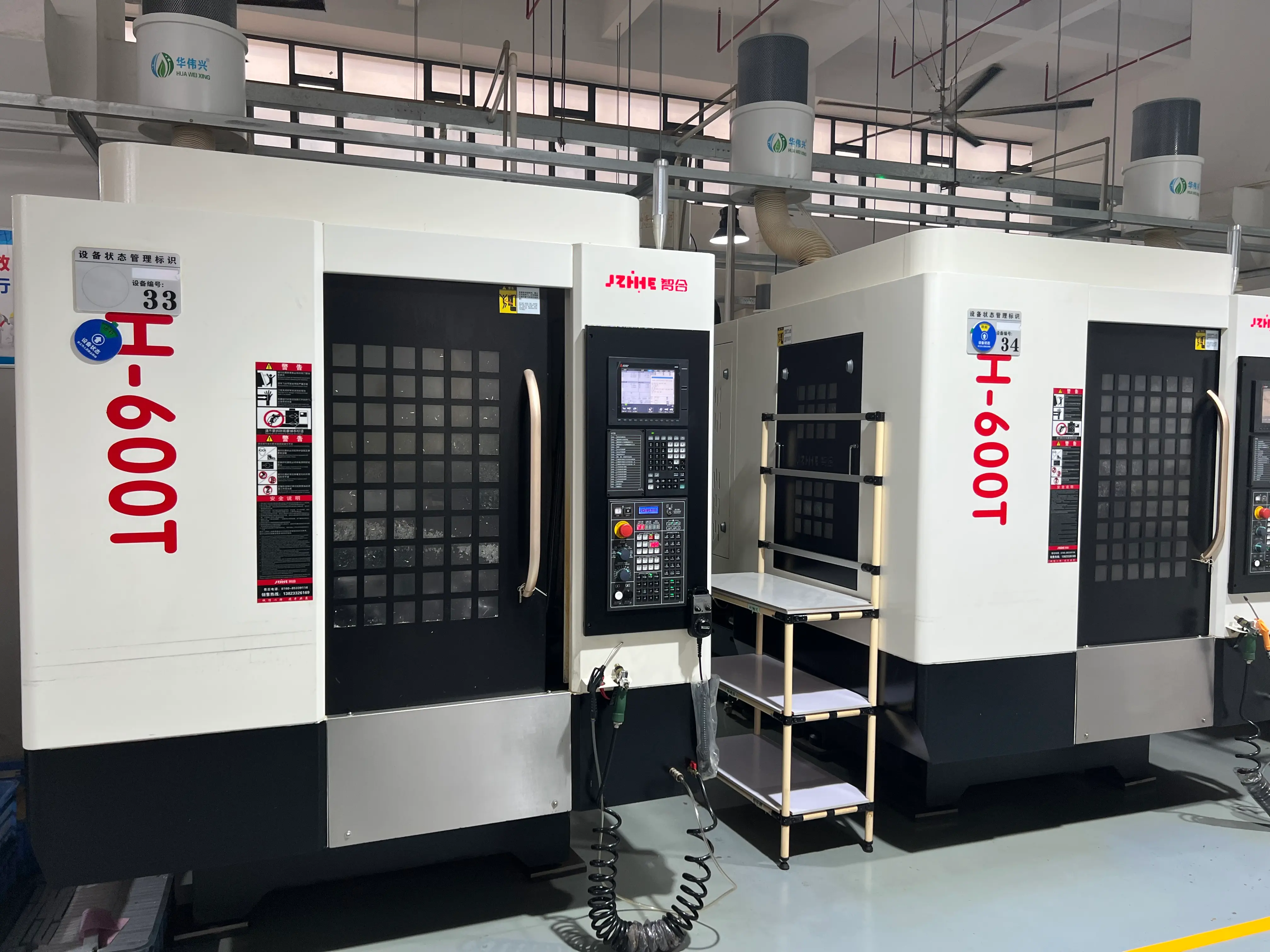
Mark the Twelve Clock-Face Zones
Divide the flange into 12 zones and label every support, clamp, probe point, heavy feature, opening, bolt group, and critical surface. Record initial and final height at each zone. This makes local bow, support reaction, chip accumulation, and temperature easier to trace.
Use the same zone labels in setup sheets, inspection reports, defect photos, and corrective actions. A note such as high at zone 2 and low at zone 8 is more actionable than a general statement that the flange is warped.
Build a Support-Reaction Map
Locate supports near stable structural regions without blocking tools or chips. Define which points establish the plane, which only prevent vibration, and how jack screws or adjustable supports are set. Record the clamp sequence and force where possible.
A large flexible flange can be forced flat on the machine and spring back after release. Measure critical face and runout conditions before clamping, during the process where useful, and after unclamping. The acceptance method must match how the customer uses the part.
| Control item | Clock-face record | Decision |
|---|---|---|
| Blank survey | Height and stock at 12 zones | Support and allowance plan |
| Clamp reaction | Movement after each clamp step | Revise force or sequence |
| Face cutting | Load, finish, and height by zone | Balance roughing and finishing |
| Bolt pattern | Position groups by sector | Check datum and thermal drift |
| Released shape | Runout and flatness after unclamping | Accept or correct the process |
Sequence the Face, Bore, and Bolt Pattern
Plan which feature establishes the next reference. Rough the face and bore with balanced stock removal, then leave a controlled finishing allowance. Define whether the bolt pattern is produced before or after final face finishing and how probing updates the coordinate system.
For a gantry CNC machine for large flanges, cross-zone relationships matter more than isolated local accuracy. Verify that tool changes, head positions, long moves, and local offsets do not create sector-to-sector steps or pattern rotation.

Control Heat Around the Circumference
Record spindle duty, coolant condition, ambient change, pauses, heavy cuts, and finishing time. Large rings and plates can develop gradients as machining moves around the circumference. Plan the order so one sector is not finished cold and its opposite sector finished after a long warm cycle without evaluation.
Use a realistic production window during the trial. Define warm-up, stabilization, compensation limits, and measurement temperature. Avoid uncontrolled offset changes that hide support or thermal problems.
Keep Chips Out of the Datum and Bolt Holes
Map pockets, bolt holes, grooves, fixtures, supports, and ledges that trap chips. Define coolant direction, air use, enclosure wash, manual cleaning, and inspection preparation. Chips under a locator or in a deep hole can create local error, damaged threads, or false probe results.
Include cleaning in cycle and safety planning. Large flanges can require operators to reach across broad surfaces; access and chip-removal tools should be designed before production release.
Use Sector-Based Probing and Inspection
Probe the datum and representative zones with an approved routine. Add independent checks for critical bores, faces, runout, bolt circles, grooves, and sealing features. Link results to zone, program, offset, tool, support condition, temperature, and time.
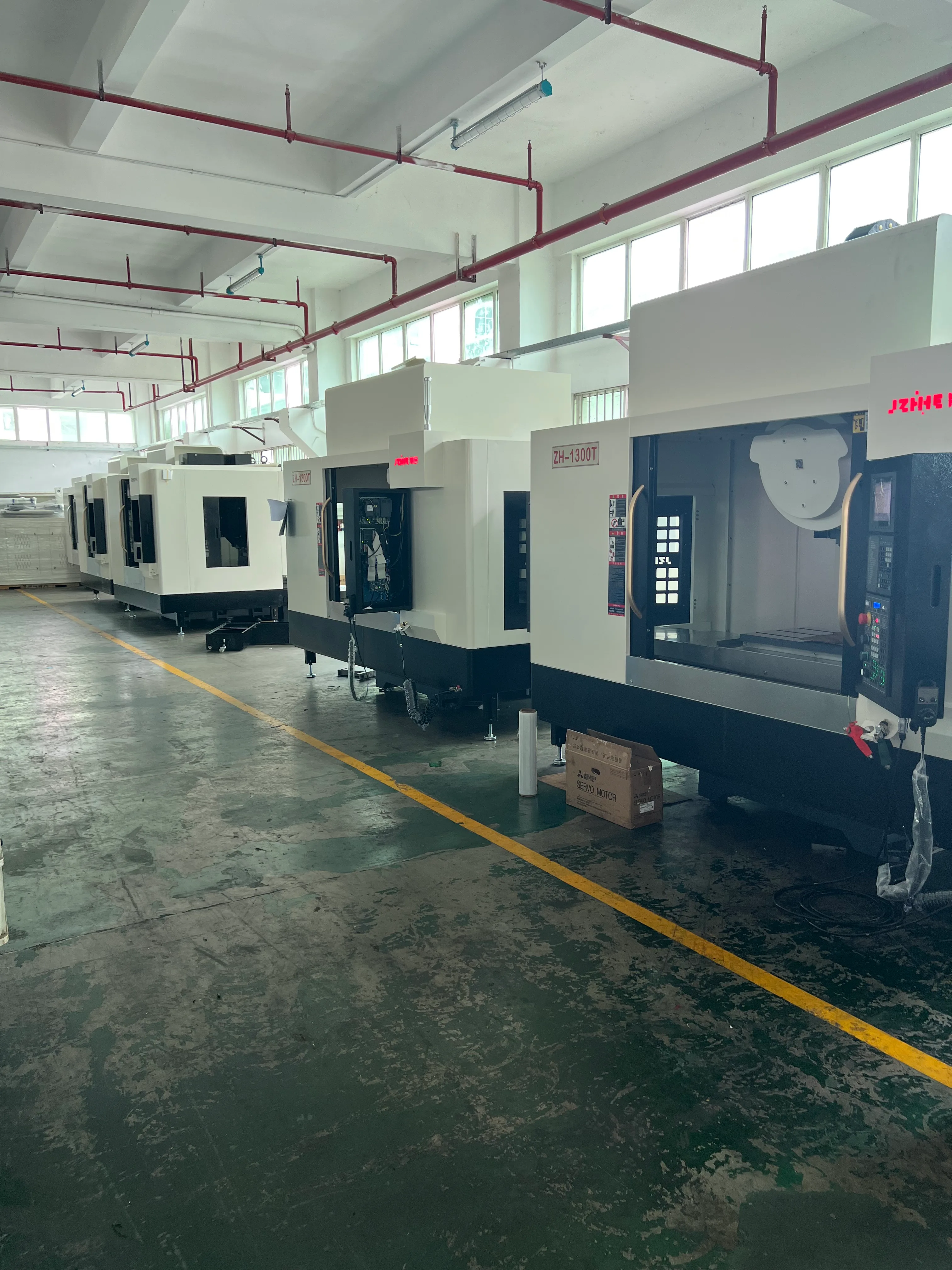
Review the gantry machining center range for architecture context, then compare the mounted envelope and zone plan with the quoted configuration.
Run a Released-Shape Trial
- Survey the blank and approve the 12-zone support map.
- Record movement through the clamp sequence.
- Run roughing and finishing with production-like tools and thermal duty.
- Inspect face, bore, pattern, and sector transitions while mounted.
- Release the clamps in a controlled sequence and remeasure the functional condition.
- Document chips, cleaning, lifting, operator work, and unresolved limits.
When a Gantry Route Is Not the Best Fit
A gantry is not automatically the best choice when the flange fits a stable turning process, when rotational machining controls the main features more directly, when a vertical or horizontal platform gives better access, or when volume cannot justify the fixture and survey effort. Compare all operations, including turning, drilling, milling, inspection, lifting, and released-part behavior.
FAQ
Why use 12 zones instead of four quadrants?
Twelve zones give finer traceability for supports, bolt groups, local bow, chips, temperature, and surface transitions while remaining practical.
Should the flange be inspected after unclamping?
Yes when the functional condition is the released shape. Mounted results alone can hide clamp-induced distortion.
Can probing replace independent inspection?
No. Probing supports process control, while final acceptance follows the agreed measurement method and uncertainty.
What lifting data is required?
Provide mass, center of gravity, lifting points, orientation, route, crane capacity, and any restrictions on finished surfaces.
Request a Clock-Face Process Review
To evaluate a gantry CNC machine for large flanges, send blank and finished drawings, diameter, thickness, mass, material, datum definition, face and bore tolerances, bolt pattern, groove details, support concept, lifting plan, batch size, thermal expectations, and inspection method. Use the contact page to request a process review, and compare the wider machining center portfolio when milling is only one stage of the route.