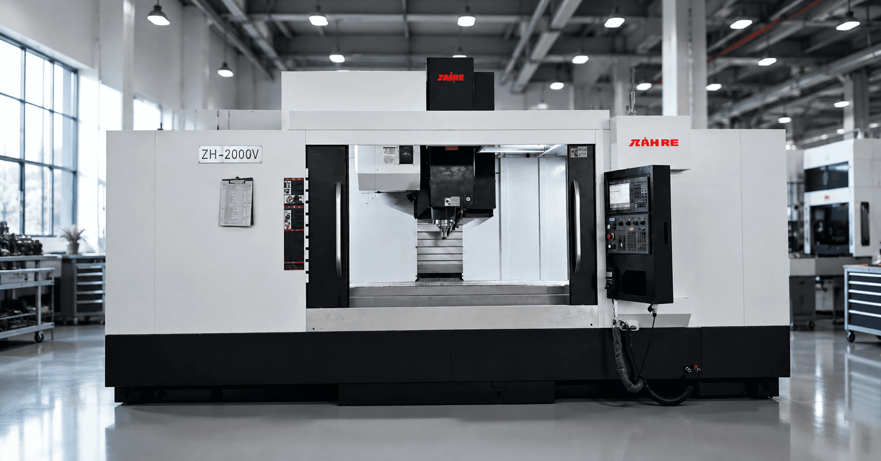
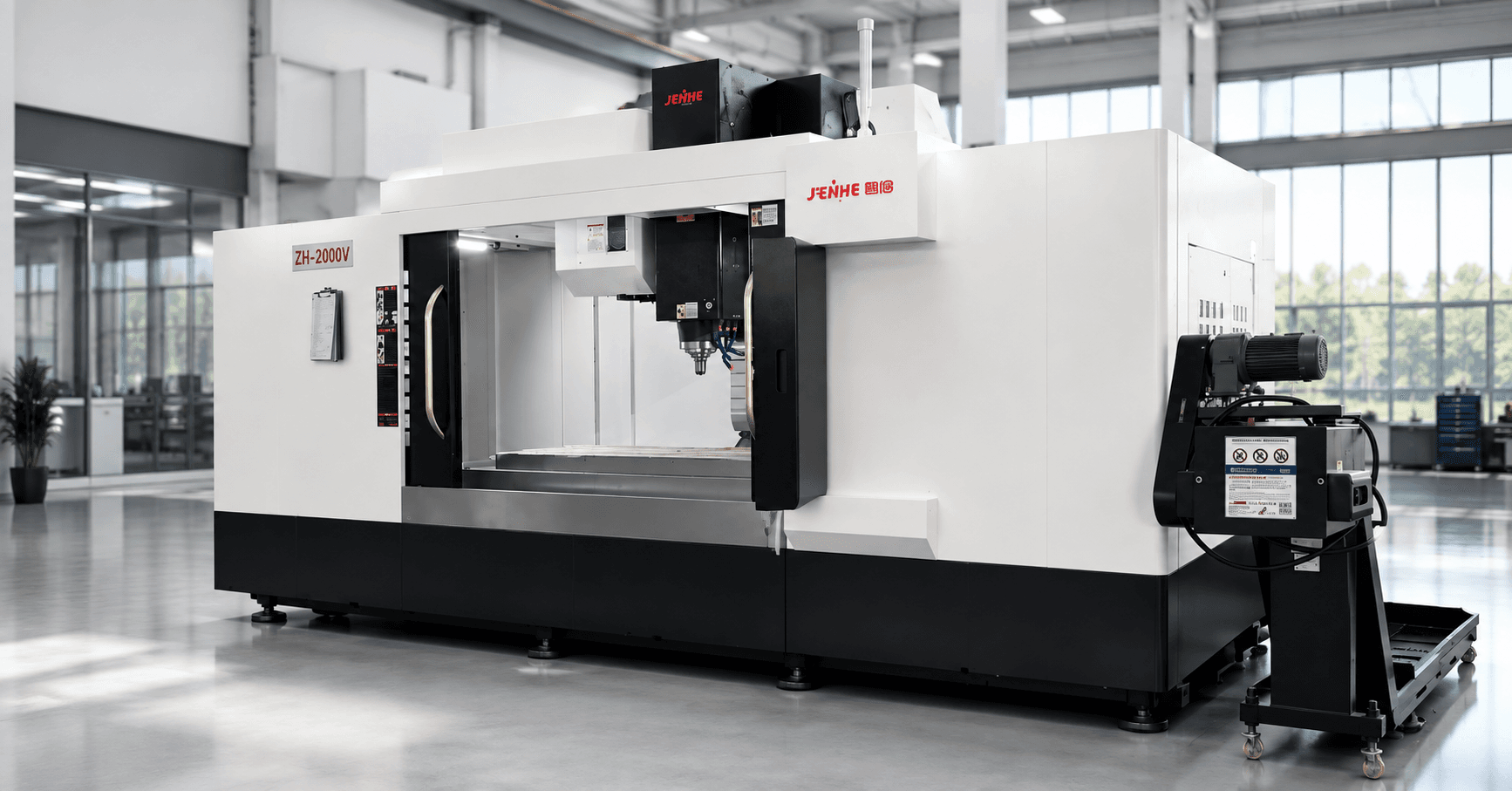
A heavy duty gantry machining center should be evaluated by proving the complete load path from the workpiece into the supports, table, machine structure, guideways, spindle, tool, and foundation. Machine weight and spindle power alone do not show whether a mounted part will remain stable through roughing, finishing, inspection, and release.
The load-path method turns a broad heavy-duty claim into a sequence of evidence. It asks where force enters, where it is reacted, how heat and chips change the condition, and whether the finished geometry remains acceptable after clamps are released.
Proof Layer 1 Describes the Real Workpiece
Record blank and finished dimensions, mass, center of gravity, material, stock distribution, casting or weldment condition, ribs, openings, lifting points, residual stress, and expected distortion. Identify the heaviest part, the longest tool engagement, and the most flexible geometry.
Include fixture mass and any angle plates, tombstones, risers, rotary units, or auxiliary supports. The table carries the complete mounted system, not the drawing mass alone.
Proof Layer 2 Maps Every Support Reaction
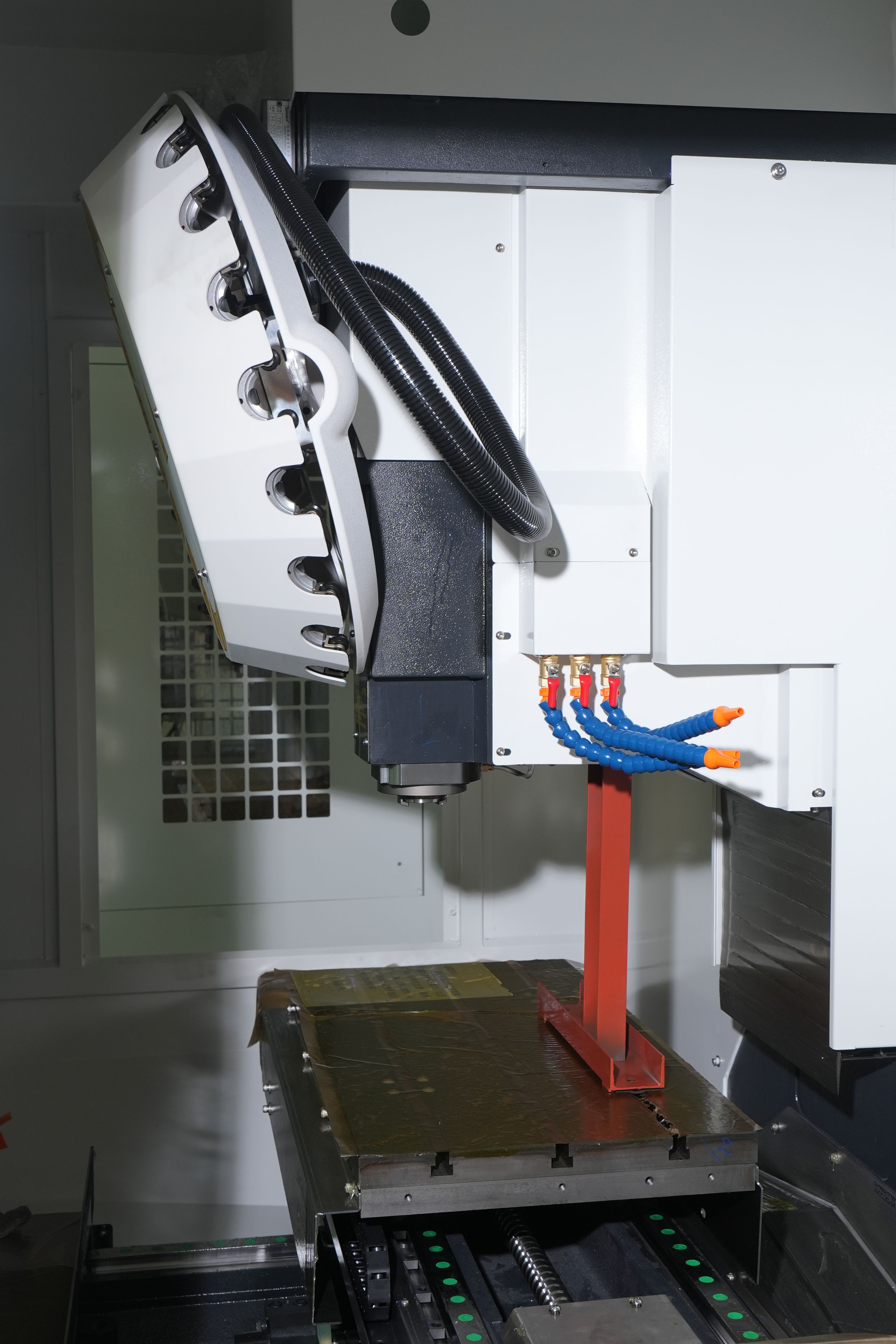
Mark the points that establish the datum plane, prevent rotation, carry weight, reduce vibration, or stabilize flexible regions. Define which supports are fixed, adjustable, hydraulic, or temporary and how their settings are verified.
Measure the blank before and after support and clamping. A flexible component can be forced into a convenient condition and spring back later. Record clamp order, force where practical, and local movement at representative zones.
Proof Layer 3 Checks the Table Load Distribution
Compare total load, footprint, point loading, overhang, center-of-gravity position, and travel-dependent condition with the quoted table limits. Ask whether the stated capacity assumes a centered and uniformly distributed load.
Consider loading equipment, skids, rollers, pallets, and temporary positioning devices. A safe and accurate route onto the table is part of the capability, especially when finished surfaces or datums can be damaged during handling.
Proof Layer 4 Follows Force Through the Bridge
Review column spacing, crossrail design, head or ram extension, guideway arrangement, drive layout, and how cutting force changes across the envelope. Identify the weakest combination of axis position, tool reach, cutter engagement, and material.
For a heavy duty gantry machining center, the test should include realistic distant positions and head extension. A short tool near the center of travel is useful for commissioning but cannot prove the complete working envelope.
| Load-path layer | Question | Proof |
|---|---|---|
| Workpiece | What mass and flexibility enter? | Blank survey and model |
| Support | Where are reactions created? | Support and clamp movement |
| Table | How is load distributed? | Mounted load map |
| Structure | Where does compliance grow? | Position-based cutting trial |
| Release | What geometry remains? | Free-state inspection |
Proof Layer 5 Matches the Spindle to Cutting Duty
Define cutter diameter, engagement, material, tool interface, spindle speed, torque range, power, duration, ram extension, and expected duty cycle. Separate peak data from sustained operation and record spindle thermal behavior.
Heavy cutting can be limited by tool, holder, fixture, workpiece, chips, or vibration before reaching motor power. The proof plan should show a stable process window, not a single dramatic cut that cannot be repeated safely.
Proof Layer 6 Controls Tool Reach and Bending
Create a tool-reach map for deep walls, pockets, bores, side features, and obstacles. Record holder gauge length, extension, cutter diameter, stick-out, interference, collision margin, and replacement availability.
Reduce reach through setup and head strategy where possible. If long tools are unavoidable, define reduced engagement, entry method, vibration monitoring, and inspection. Tool bending belongs in the load path and can dominate local error.
Proof Layer 7 Adds the Thermal Route
Record warm-up, spindle duty, ambient change, coolant condition, pauses, heavy roughing, finishing order, and measurement timing. Large parts and long cycles create gradients that can move datums and surfaces across the work envelope.
Define stabilization rules and allowable compensation. Avoid offset changes that hide support, tool, or structural problems. The same trial should distinguish predictable thermal drift from sudden process instability.
Proof Layer 8 Keeps Chips Out of Reactions
Map where chips accumulate on the part, fixture, table, supports, telescopic covers, and enclosure. Define conveyor, flushing, coolant direction, air, manual cleaning, and safe access. Include chip volume over the full roughing interval.
Chips under a support or locator can change the load path. Chips left in deep cavities can also create tool recutting, false probing, lifting hazards, or downstream cleaning work.
Proof Layer 9 Measures Mounted and Released Geometry
Inspect the functional datums, faces, bores, patterns, transitions, and free-state condition using the agreed method. Link results to support settings, axis zone, tool, thermal state, and time. Define uncertainty and environmental limits.
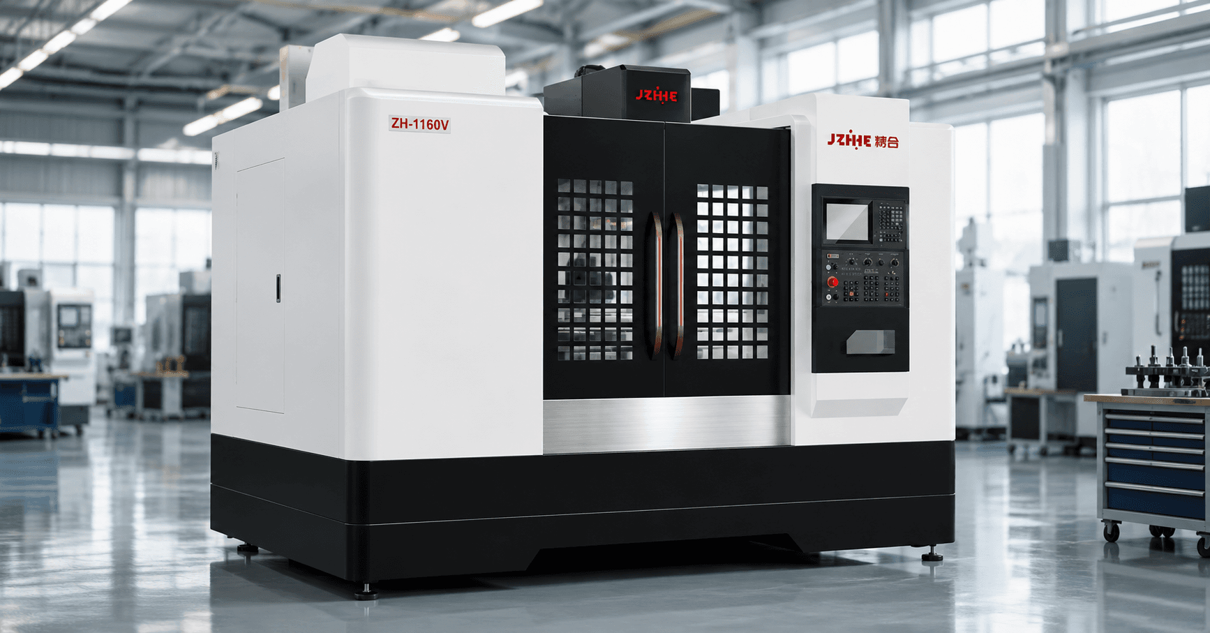
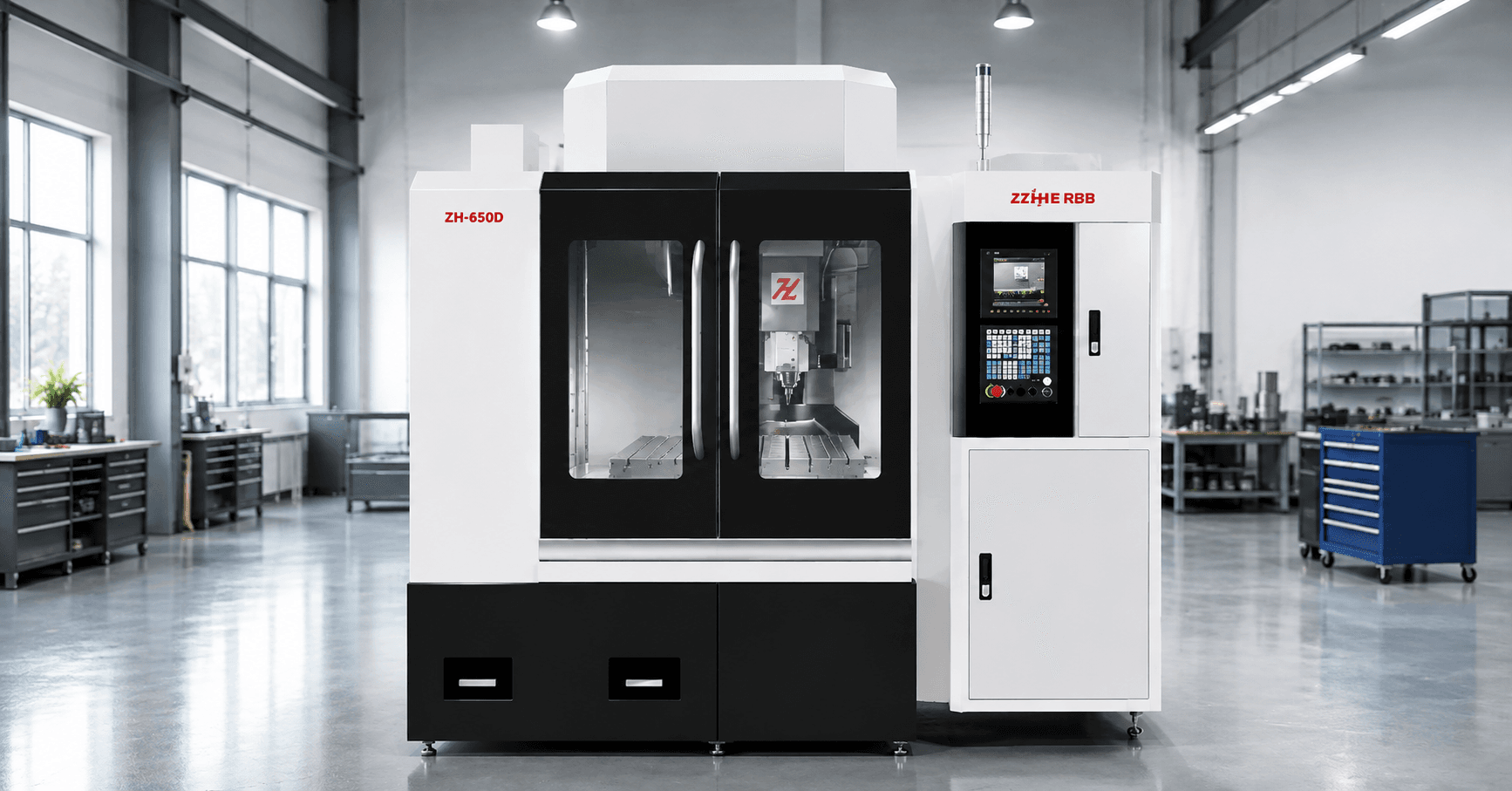
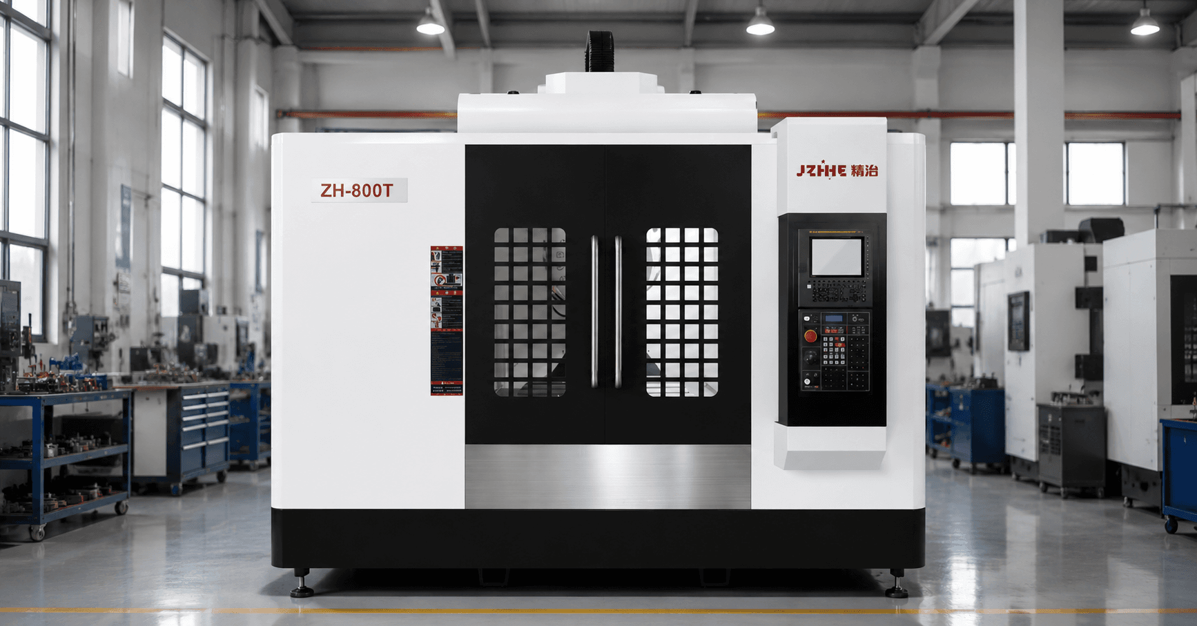
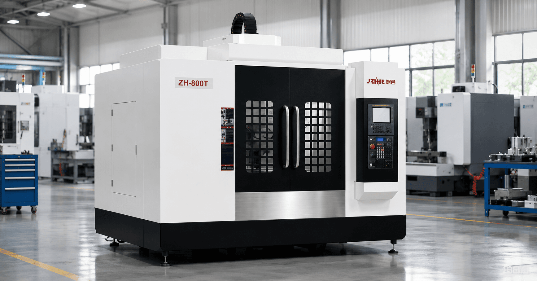
Review the gantry machining center range for architecture context, then require the acceptance trial to cover the mounted envelope and released behavior that matter to production.
Execute the Load-Path Proof Stack
- Approve the workpiece, fixture, lifting, and support maps.
- Survey movement during support and clamp application.
- Run representative roughing at critical envelope positions.
- Continue through thermal stabilization and finishing.
- Verify chips, tool reach, probing, and operator access.
- Inspect while mounted, release in a controlled sequence, and inspect again.
Where Heavy-Duty Architecture Is Not Justified
A gantry route is not automatically best when parts fit a smaller stable platform, turning controls the main geometry, cutting duty is light, annual use is low, or loading and fixture complexity dominate. Extra mass and envelope can increase floor, foundation, transport, and operating requirements.
Choose the lightest architecture that proves the required load path with acceptable margin. Capability without utilization can weaken the investment case.
FAQ
Does machine weight prove rigidity?
No. Weight can support stability, but structural layout, position, guideways, ram extension, tool reach, support, foundation, and process conditions determine practical behavior.
Should maximum table load be used as the normal target?
No. Treat it as a limit under defined distribution conditions and verify the actual mounted mass, center of gravity, point loads, and required performance.
Why inspect after unclamping?
Released inspection shows whether support and clamp forces hid workpiece distortion that will appear in assembly or service.
What trial cut is most useful?
Use a representative material, tool reach, engagement, duration, envelope position, and quality requirement from the intended workpiece family.
Send a Heavy-Load Proof Package
To evaluate a heavy duty gantry machining center, send blank and finished drawings, mass and center of gravity, material, stock condition, fixture and support concept, lifting plan, cutter sizes, spindle duty, tool reach, tolerances, cycle expectations, thermal conditions, and inspection method. Use the contact page for an engineering review and compare the full platform range when the load path may fit another machine architecture.