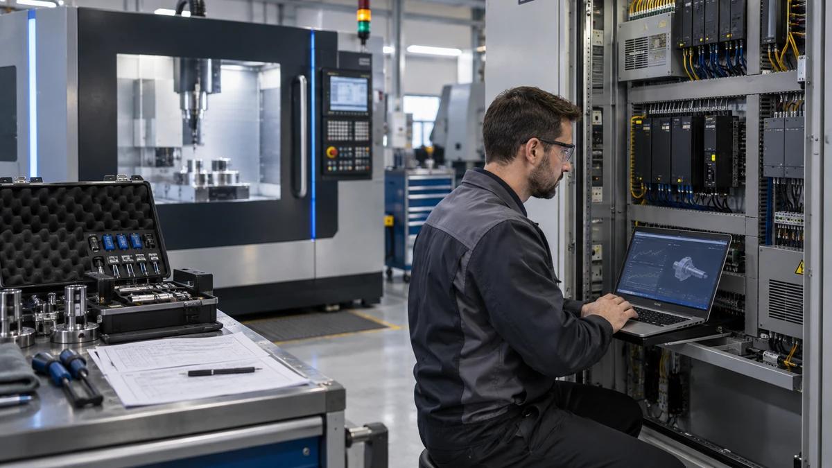
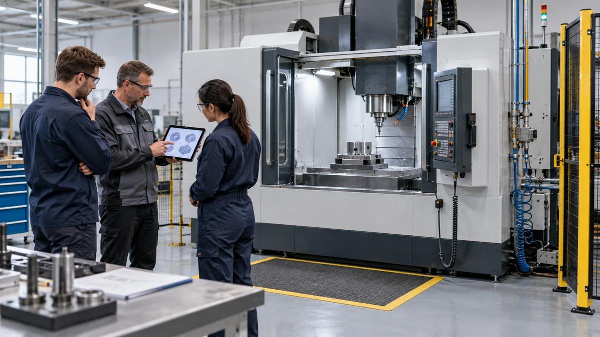
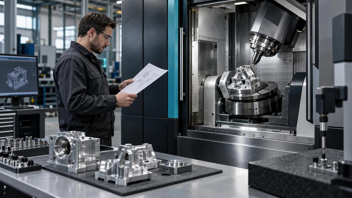
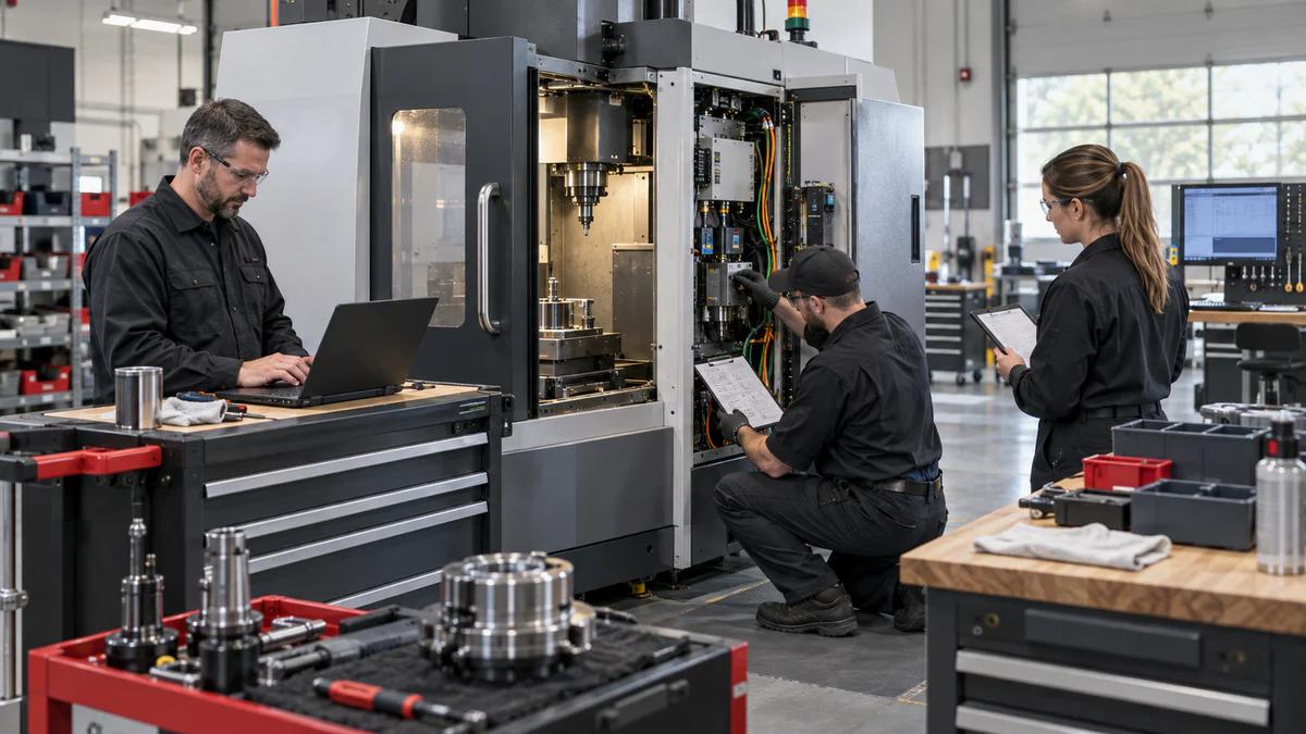
A mold milling machining center should be evaluated by how clearly the process explains surface failures, not by one polished sample or one roughness number. Zhihe CNC uses a five-defect atlas covering witness lines, chatter, waviness, form error, and corner damage to trace each visible symptom back through stock, tools, programs, kinematics, heat, inspection, and hand finishing.
The atlas is designed for mold shop owners, CAM programmers, process engineers, quality teams, and buyers. It separates what the machine can influence from fixture, blank, tool assembly, digital stock, cutting strategy, environment, measurement, and polishing conditions.
Start the Autopsy Before Polishing
Preserve the incoming stock model, material, hardness, stress-relief history, datum condition, fixture, tools, holders, runout, program, controller settings, thermal state, coolant, measurement, photographs, lighting, and defect map. Do not blend away the evidence before diagnosis.
Zhihe CNC recommends assigning every defect a location, direction, scale, process stage, and first observed time.
Defect 1: Witness Lines Between Toolpaths
Witness lines may come from stepovers, tool changes, rest machining boundaries, orientation transitions, tool length differences, runout, wear, offsets, smoothing, postprocessor behavior, or local deflection. Compare the mark with the programmed boundary and actual tool history.
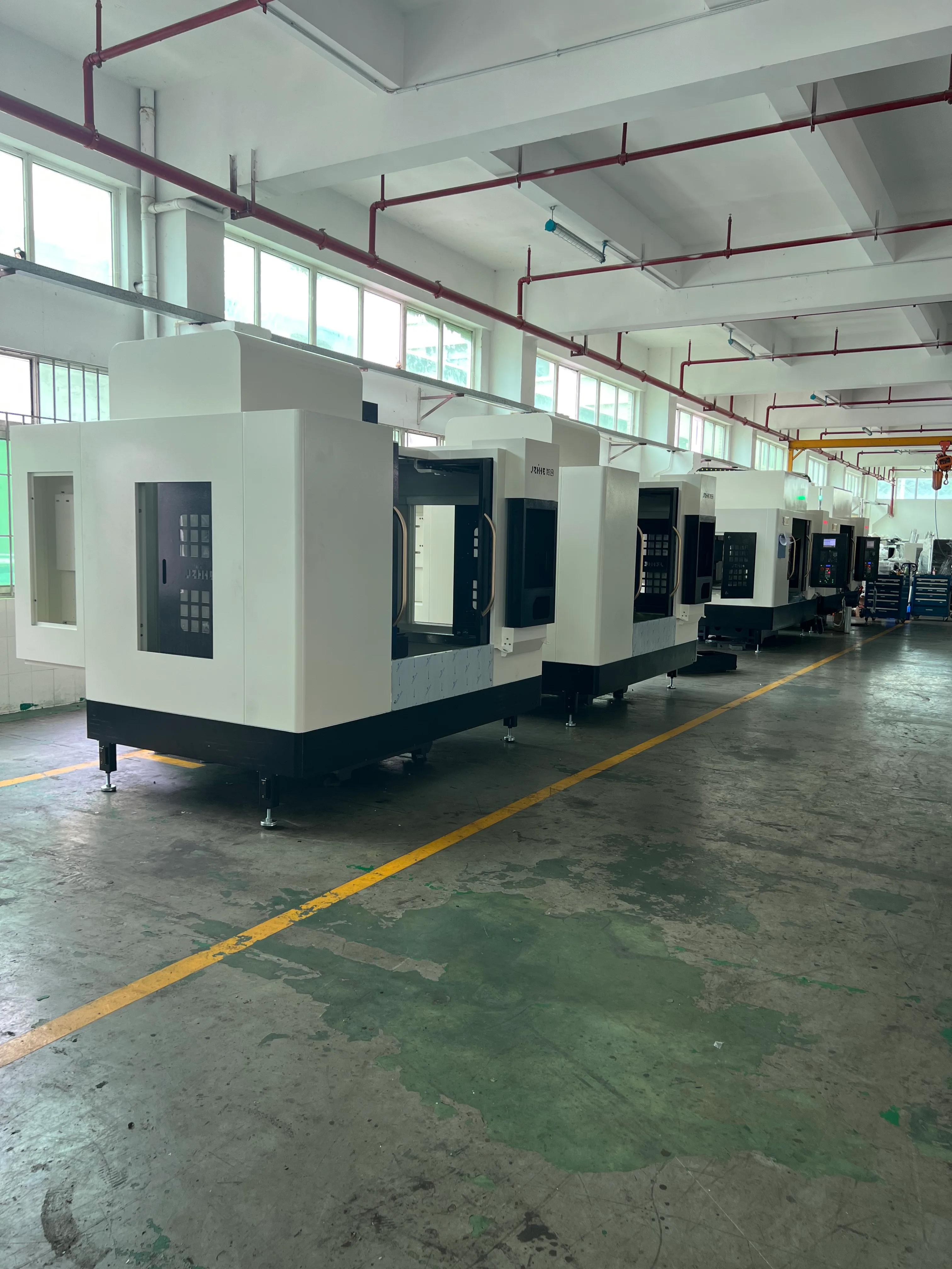
Read Witness Lines With a Boundary Table
| Observed line | Likely evidence | Controlled test |
|---|---|---|
| At tool change | Offsets and runout | Repeat with verified assembly |
| At rest path | Digital and real stock | Measure incoming stock |
| At orientation shift | Post and kinematics | Trace rotary and TCP state |
| At shallow-steep border | Strategy transition | Compare contact and stepover |
| After restart | Reference and stock state | Rehearse controlled recovery |
The table prevents cosmetic repair from replacing root-cause evidence.
Defect 2: Chatter Bands
Chatter depends on tool diameter, projection, holder, runout, balance, spindle speed, tooth passing, engagement, direction, local stiffness, stock, fixture, machine structure, and control behavior. Mark where bands begin and end relative to geometry and engagement.
A mold milling machining center trial should include the long or small tools that actually create risk, not only a short rigid finishing cutter.
Separate Forced Vibration From Regenerative Chatter
Repeatable marks tied to spindle, tooth, axis, coolant, or external vibration may indicate forced excitation. Regenerative chatter often changes strongly with speed, engagement, tool projection, and local stiffness. Preserve sound, surface, tool, and parameter evidence.
Zhihe CNC recommends controlled single-variable trials only after safety, collision, and stock conditions are reviewed.
Defect 3: Waviness Across a Cosmetic Surface
Waviness can reflect path spacing, axis reversal, smoothing, feed fluctuation, acceleration, thermal drift, tool deflection, fixture movement, or measurement filtering. One low roughness reading at an easy point cannot approve the whole surface.
Map wavelength, direction, amplitude, location, and relation to machine axes or toolpath. The pattern often identifies which evidence to inspect next.
Use a Surface Evidence Matrix
| Surface attribute | Measurement question | Do not confuse with |
|---|---|---|
| Roughness | What short-scale texture exists? | Form |
| Waviness | What medium-scale pattern repeats? | Scallop alone |
| Form | Does geometry match CAD? | Best-fit hiding |
| Blend | Are transitions continuous? | One-point finish |
| Visual class | What appears under defined lighting? | Instrument value only |
State instrument, filter, alignment, environment, sample, and acceptance rule for every class.
Defect 4: Form Error That Survives Good Finish
A surface can look smooth while being dimensionally wrong. Trace datum, stock, fixture distortion, tool radius and length, runout, deflection, kinematic calibration, thermal state, compensation, program model, controller mode, and inspection alignment.
The ISO 230-2 search reference provides positioning context; the buyer still needs feature- and condition-specific evidence.
Check Digital Stock Against Physical Stock
Rest machining assumes the software knows what material remains. Earlier tool deflection, stock variation, fixture movement, omitted operations, wrong tool geometry, or program changes can make that assumption false. Measure or verify critical stock before high-value finishing.
Zhihe CNC recommends a release gate between semi-finishing and finishing for datum, stock, access, tool, and program readiness.
Defect 5: Corner Damage and Overworked Transitions
Corners can show excessive engagement, slowdowns, dwell, tool-center behavior, wrong rest stock, cutter mismatch, poor approach, insufficient radius, local vibration, or polishing damage. Separate sharp design intent from process-created sharpness.
Use a corner risk map covering internal radii, ribs, deep intersections, parting surfaces, inserts, and cosmetic transitions.
Control the Thermal Sequence Before Final Passes
Record roughing duty, cooling delay, spindle warm-up, ambient range, coolant condition, axis activity, reference checks, and finishing duration. If the mold leaves the fixture or machine, define how it returns and is re-established.
A mold milling machining center should be tested through the thermal sequence intended for production, not only after an ideal stabilization period.
Turn Polishing Into a Measured Handoff
Record incoming surface, uniform allowance, defect zones, forbidden repair, edge protection, method, labor, corrections, final geometry, and return-to-machining decision. Polishing should not erase evidence or move a surface outside form limits.
Zhihe CNC uses a return gate when a defect needs geometry correction, stock restoration, or a controlled new toolpath rather than more hand work.
Validate the Complete Mold Trial
Freeze material, hardness, stock, fixture, tools, programs, thermal state, coolant, inspection, visual lighting, polishing boundary, limits, sample, and retest. The ISO 10791 series reference provides machining-centre test context, while the mold trial remains application-specific.
Include at least one difficult reach, transition, and recovery event.
Audit the Mold Milling Machining Center Failure Atlas
After several molds, compare defect types, locations, tool assemblies, program revisions, thermal conditions, stock maps, inspection, polishing hours, returns to machining, and corrective actions. Retire fixes that worked only under one unrecorded condition.
The mold milling machining center should reduce unexplained hand work as evidence improves. Zhihe CNC converts recurring failure signatures into tool, program, fixture, inspection, and release standards.
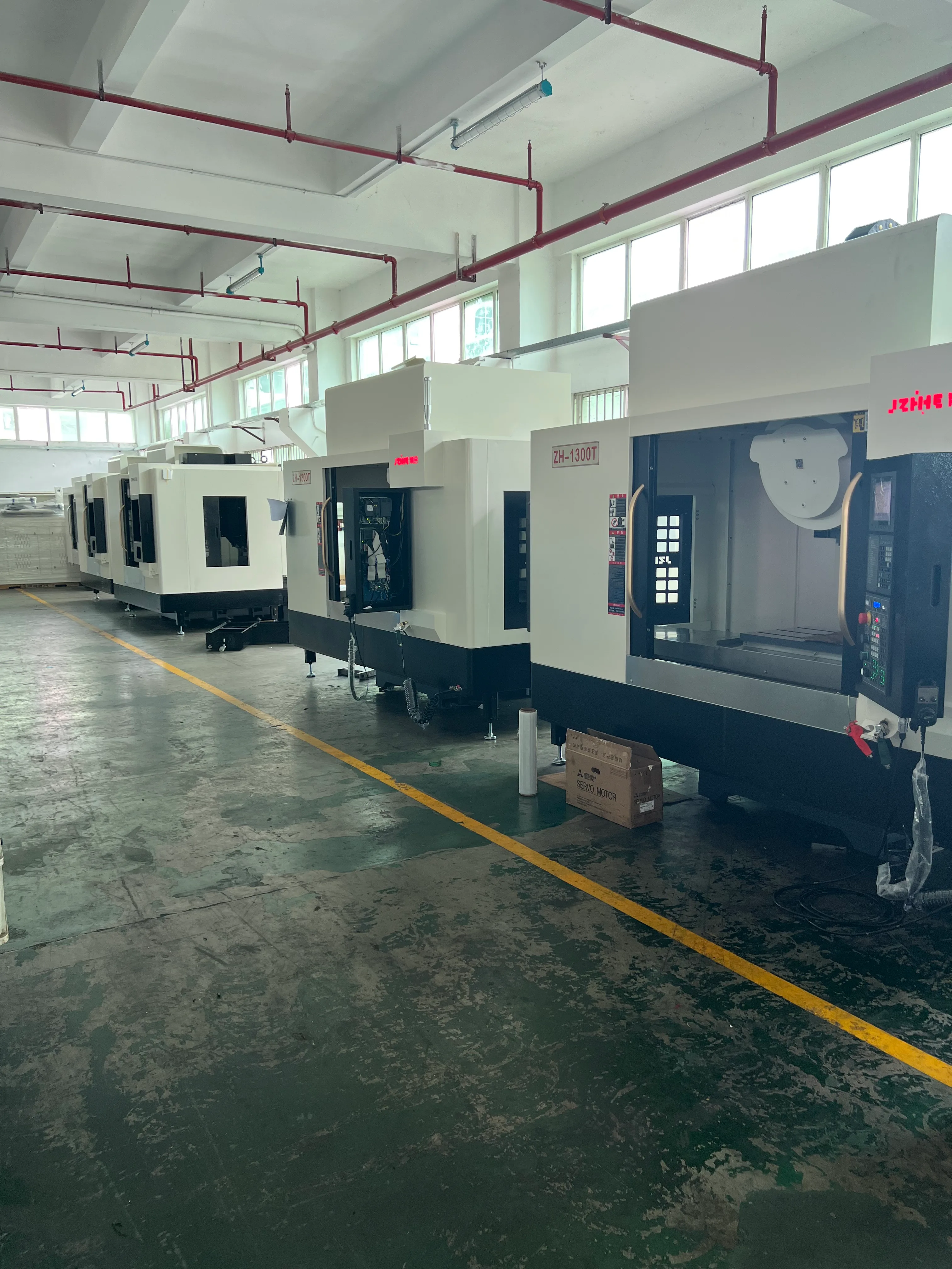
Turn the Failure Atlas Into a Preventive Standard
Prevention begins by converting repeated diagnoses into release checks. For each defect family, define the incoming stock condition, tool assembly limits, runout method, permitted projection, program revision, thermal window, fixture state, inspection method, and response threshold. Link the standard to the mold zones where the failure has occurred.
Use a layered check rather than one final inspection. Confirm stock and datum before semi-finishing, verify remaining material and access before finishing, check tool and thermal state before cosmetic passes, and preserve a surface map before polishing. Each gate should stop the process when the next operation would erase evidence or increase repair cost.
A mold milling machining center standard should also distinguish mandatory control from diagnostic guidance. Mandatory limits release or hold the job. Diagnostic guidance suggests the next evidence to inspect without encouraging operators to change several variables at once.
Zhihe CNC recommends reviewing the atlas monthly by part family, tool group, program strategy, machine state, and polishing return. Measure recurrence, detection stage, repair hours, geometry impact, and whether the corrective action survived the next comparable mold.
Keep approved examples and rejected examples under consistent lighting and measurement. Visual references help teams discuss texture and blends, but they must stay linked to form, roughness, waviness, and process records rather than becoming subjective substitutes.
The preventive standard becomes valuable when new programmers, operators, inspectors, and polishers can recognize a failure signature and follow the same evidence trail. It should reduce dependence on memory while preserving a clear route for unusual surfaces that need engineering review.
Know What the Failure Atlas Cannot Guarantee
The atlas cannot guarantee every mold material, hardness, geometry, tool, program, temperature, polish, or inspection result. It creates a tested diagnostic method and makes assumptions visible. New extremes of reach, stock, finish, or form may require targeted trials.
FAQ
Why inspect before polishing?
Polishing can remove or move the evidence needed to identify toolpath, stock, vibration, or geometry causes.
Does low roughness prove a good mold surface?
No. Waviness, form, blend, witness lines, local defects, and visual class require separate evaluation.
What commonly creates a witness line?
Tool changes, rest boundaries, orientation changes, offsets, runout, wear, smoothing, deflection, or recovery can contribute.
How is chatter diagnosed safely?
Preserve evidence, review collision and stock, then use controlled changes in speed, engagement, projection, or stiffness.
Why compare digital and physical stock?
Rest machining fails when actual remaining material differs from the software model.
Can a smooth surface still have form error?
Yes. Texture and geometry are different; datum, thermal, tool, kinematic, and inspection errors can remain.
When should polishing return a mold to machining?
Return it when geometry, stock, deep defects, or controlled surface restoration cannot be achieved safely by hand.
Which thermal data should be preserved?
Keep roughing duty, delay, warm-up, ambient, coolant, axis activity, reference checks, and finishing duration.
What makes a representative mold trial?
Use realistic material, hardness, stock, reach, transitions, tools, thermal sequence, inspection, and polishing boundary.
What should a mold shop send Zhihe CNC?
Send mold CAD, material, hardness, stock, zones, tools, surfaces, tolerances, inspection, polishing, and defect history.
Build the Surface-Failure Atlas With Zhihe CNC
To evaluate a mold milling machining center, send Zhihe CNC the mold model, material, hardness, stock condition, fixture, tool assemblies, surface classes, tolerances, inspection, polishing route, and defect examples. Review the milling machining center range, the Zhihe CNC profile, and the contact page before defining a diagnostic trial.