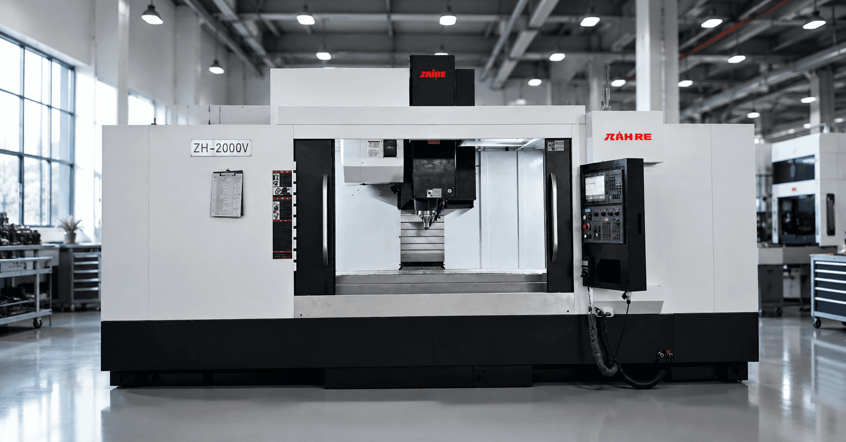
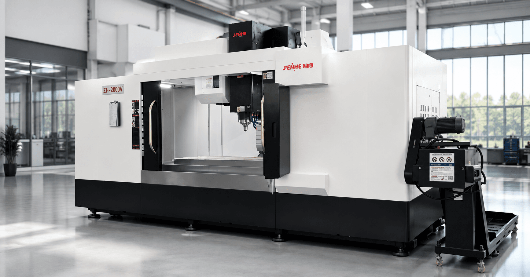
A precision engraving milling machine should be evaluated by linking visible defects to tool runout, vibration, thermal state, chip recutting, tool reach, corner engagement, burr formation, and inspection method. A glossy demonstration surface is not enough because lighting, material, tool age, finishing direction, and post-processing can hide the real process window.
A defect atlas turns surface observations into controlled experiments. It helps buyers distinguish machine-related limits from tooling, holder, program, fixture, material, coolant, cleaning, and measurement effects.
Atlas Entry 1: Repeating Tool Marks
Regular lines or periodic patterns can come from runout, spindle behavior, flute imbalance, interpolation, axis motion, feed per tooth, holder condition, or finishing step-over. Record the mark direction, spacing, tool, spindle speed, feed, engagement, and machine position.
Check holder cleanliness, collet or shrink condition, tool projection, runout near the cutting edge, and tool balance where relevant. Rotate one variable at a time. If mark spacing changes with spindle speed or feed, the pattern provides evidence about the source.
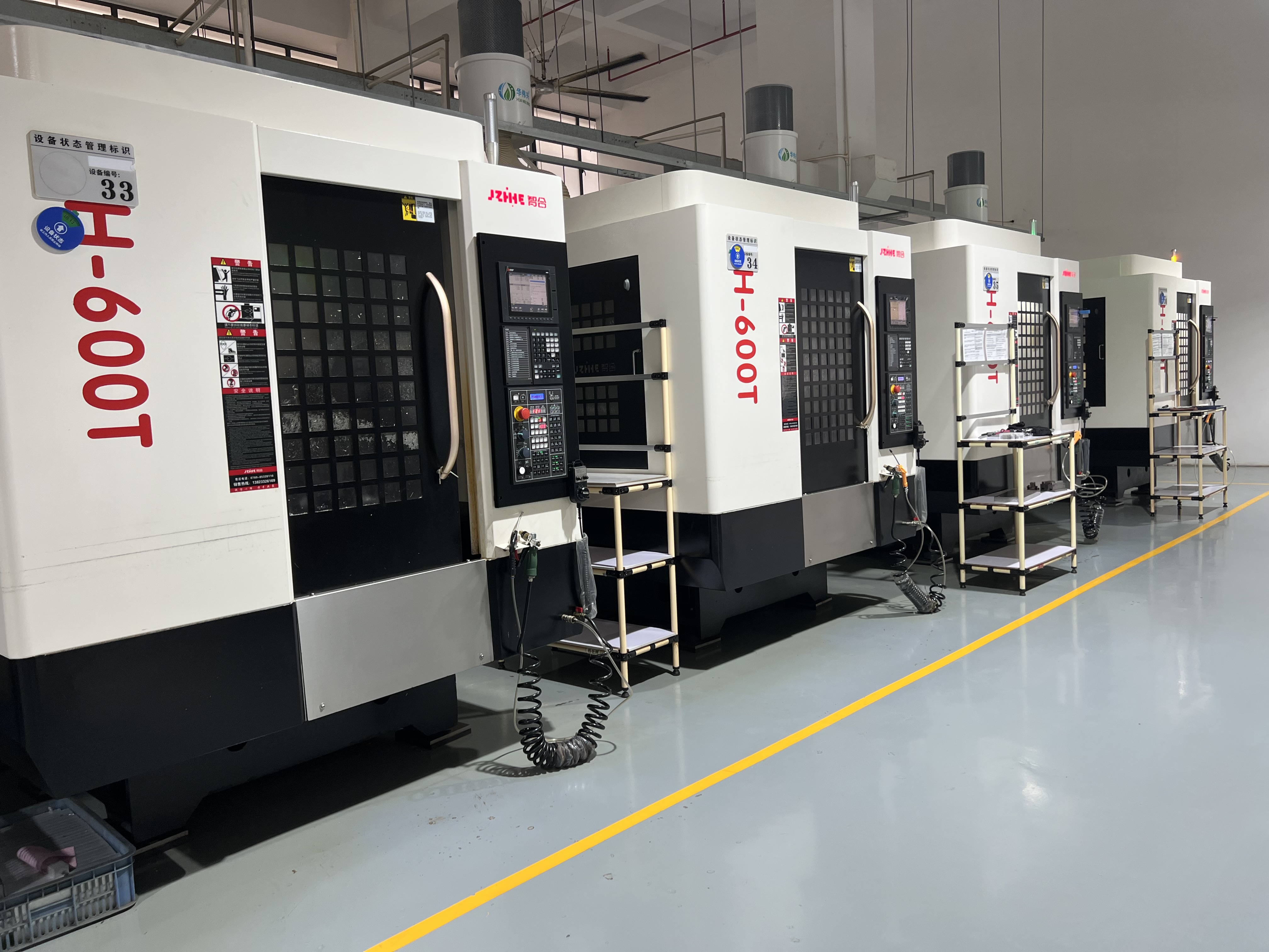
Atlas Entry 2: Chatter in Corners or Deep Features
Corner engagement can rise sharply even when straight-wall cutting is stable. Deep features add tool and holder deflection. Map where chatter begins, tool reach, holder clearance, corner radius, radial engagement, axial depth, spindle load, and sound or vibration observations.
Use toolpath smoothing, controlled engagement, rest machining, shorter tools, tapered or reinforced holders, staged reach, and reduced abrupt direction changes. Verify that collision avoidance does not force an unnecessarily weak assembly.
Atlas Entry 3: Heat Tint, Smearing, or Built-Up Edge
Heat-related defects can result from a dull tool, rubbing, insufficient chip load, recutting, poor lubrication, unsuitable coating, long engagement, or unstable coolant delivery. Examine the tool and chips as well as the workpiece.
Record material specification and stock condition. Aluminum, hardened mold materials, copper alloys, graphite, and other materials require different strategies. Do not transfer cutting data from a visually similar material without a controlled trial.
| Defect | Variables to isolate | Evidence |
|---|---|---|
| Periodic lines | Runout, flute load, speed, feed, axis motion | Mark spacing and tool measurement |
| Corner chatter | Engagement, reach, holder, path transition | Location map and load trend |
| Smeared surface | Tool edge, chip load, heat, lubrication | Tool image, chip sample, surface review |
| Floor ridges | Step-over, tool tilt, runout, flatness | Profile and toolpath record |
| Edge burr | Exit direction, support, wear, material | Burr location and downstream time |
Atlas Entry 4: Floor Ridges and Blend Errors
Ridges can appear where toolpaths overlap, where a finishing tool does not match the programmed geometry, or where several orientations meet. Record tool radius, measured tool length and diameter, runout, step-over, path direction, stock allowance, probe or offset method, and the location of blends.
Use a precision engraving milling machine with a proven calibration and tool-control process, but keep postprocessor and programming evidence in scope. A mechanically capable machine cannot correct a wrong tool model, offset, tolerance setting, or blend strategy.
Atlas Entry 5: Burrs on Fine Edges
Fine text, slots, vents, electrodes, mold details, and thin edges can develop burrs that are expensive to remove without changing geometry. Map burr direction and height by feature. Review cutting direction, exit condition, tool sharpness, support, remaining stock, material grain or structure, and cleaning.
Measure manual deburring and reinspection time. A slightly longer finishing path can lower accepted-part cost if it removes variable handwork and prevents damaged details.
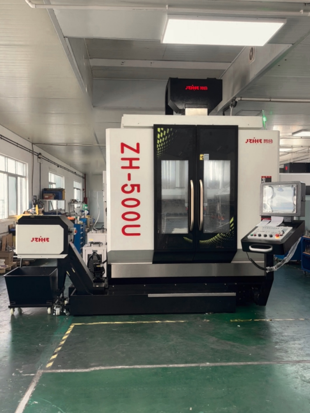
Build a Micro-Tool Stability Loop
- Identify the smallest tool, longest reach, weakest feature, and most sensitive surface.
- Measure holder and tool runout using a controlled method.
- Freeze tool identity, projection, cutting data, path, coolant, and material.
- Run time-sequenced samples through the expected tool-life window.
- Inspect the tool, chips, surface, burrs, dimensions, and downstream work.
- Define warning and replacement rules before visible failure.
Review the milling machining center range and the high-speed milling platform as configuration references. Final selection still depends on the actual material, tool size, geometry, and finish target.
Use a Controlled Light-Path Inspection
Surface appearance changes with light angle, intensity, magnification, cleaning, and viewing direction. Define the inspection light, distance, orientation, magnification, surface preparation, comparator, and acceptance examples. Add profile, roughness, form, or dimensional measurement where appearance alone cannot describe function.
Know the Boundary of the Atlas
A defect atlas narrows causes but does not replace machine calibration, metrology, material verification, or engineering analysis. Not every visible pattern is generated by the machine; polishing, blasting, coating, washing, handling, and photography can add or hide marks. Claims about mirror finish or micron-level accuracy must be tied to the specific configuration, part, condition, and measurement.
FAQ
Is spindle speed the main selection criterion?
No. Runout, balance, thermal behavior, axis motion, toolholding, control response, fixture, chips, and process evidence also shape fine-feature quality.
Why can a sample look better under different lighting?
Directional light emphasizes or hides tool marks. Inspection conditions must be standardized for a fair comparison.
Should micro-tools be replaced only after breakage?
No. Use wear, load, surface, burr, dimensional, or part-count rules to replace tools before unstable quality or breakage.
Can polishing be included in a machining trial?
Only if it is separately identified. Otherwise, polishing can hide the surface produced directly by the milling process.
Send a Defect Atlas for Review
To evaluate a precision engraving milling machine, send the drawing, material and hardness, smallest tool, longest reach, finish and form targets, defect photos with scale, toolpath direction, current cutting data, holder details, batch size, inspection method, and downstream finishing. Use the contact page to request a stability and trial review.