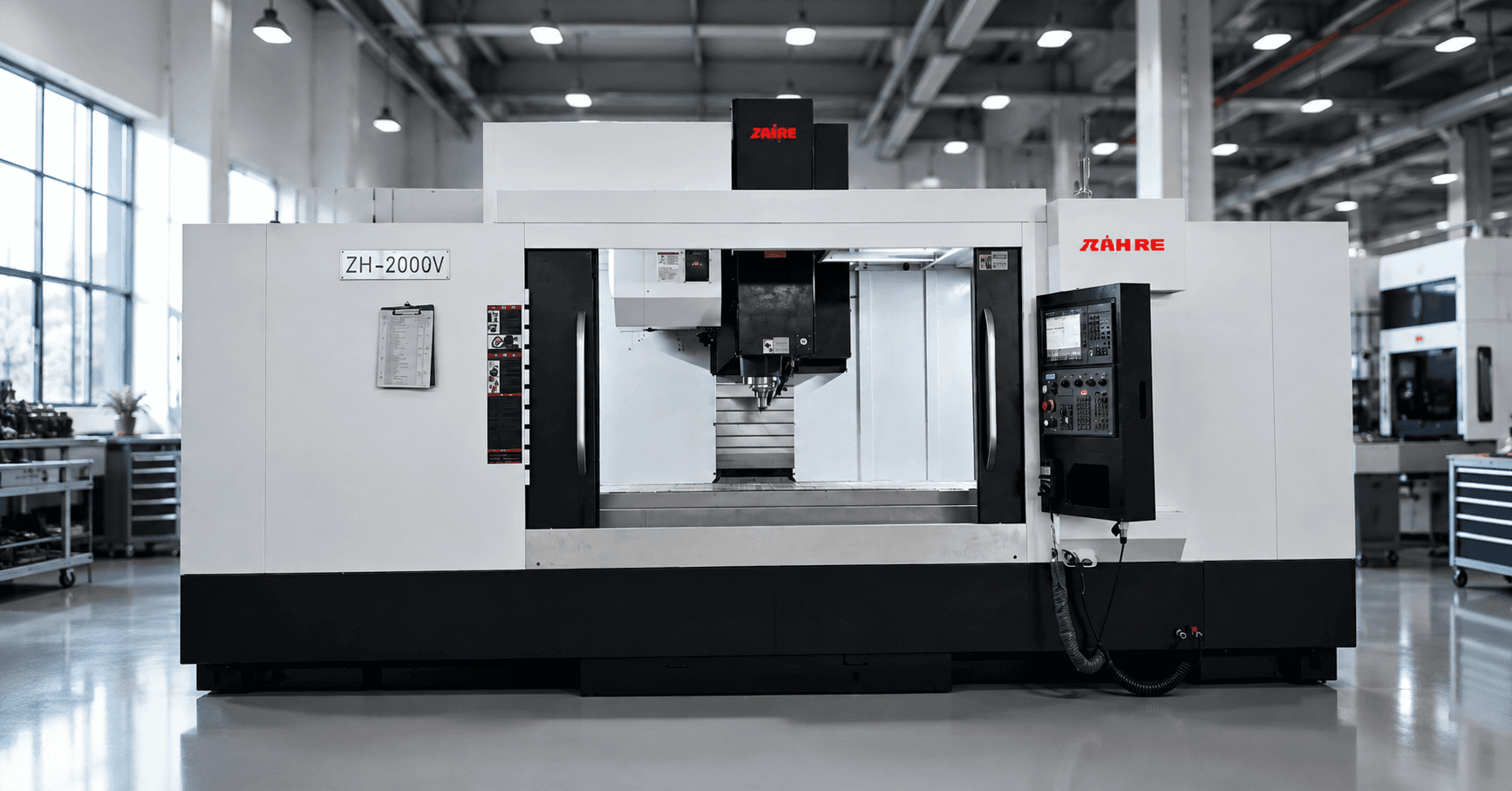
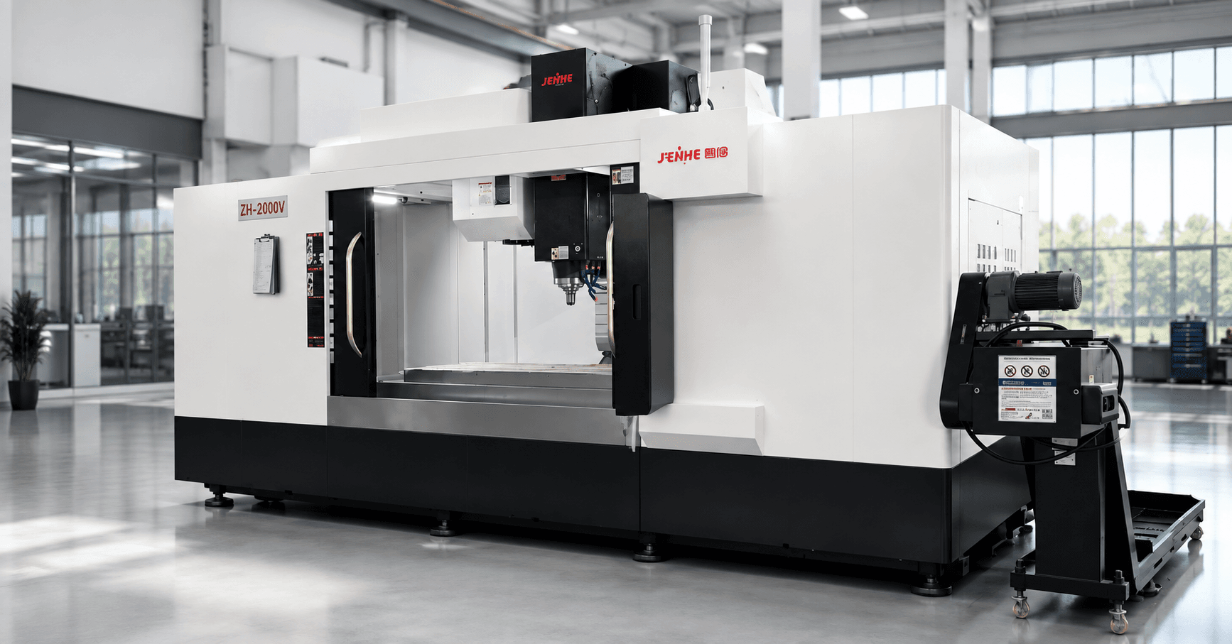
A 5 axis machining center for precision molds creates value when it removes risky setups, improves tool access, and protects the final surface—not simply because it can move five axes. The buying decision should begin with mold features and process sequence: which surfaces require simultaneous motion, which can use indexed 3+2 machining, which should stay on a three-axis or gantry machine, and which require electrodes or separate finishing.
This guide is organized as a feature-routing matrix. It helps moldmakers assign each feature to the right machining mode, define the datum strategy, control collision and tool-reach risk, and build an acceptance part that represents the real mold workflow.
Route Each Mold Feature Before Selecting the Machine
| Mold feature | Likely machining mode | Main reason | Key risk |
|---|---|---|---|
| Open cavity floor | Three-axis or indexed 3+2 | Simple access and efficient toolpaths | Thermal and finishing consistency |
| Steep walls and draft surfaces | Indexed 3+2 or simultaneous five-axis | Shorter tool and better contact angle | Rotary accuracy and surface blending |
| Deep ribs and narrow slots | Indexed orientations plus specialized tooling | Reduce reach and improve clearance | Collision, chatter, chip evacuation |
| Undercuts and side details | Five-axis, angled head, or electrode | Reach geometry without extra setups | Holder interference and verification |
| Cooling and angled holes | Indexed drilling | Accurate compound-angle access | Datum transfer and drill wander |
| Parting surfaces | Three-axis or five-axis finishing | Protect flatness and transition quality | Stock consistency and tool marks |
The matrix prevents overbuying. A mold family dominated by large open cavities may need travel, rigidity, thermal control, and finishing stability more than continuous five-axis motion. A family with deep compound features may gain substantially from tilting the workpiece or tool to keep cutters short. The existing three-axis versus five-axis comparison can help frame that first architecture decision.
Choose 3+2 or Simultaneous Motion Feature by Feature
Use indexed 3+2 when orientation solves the problem
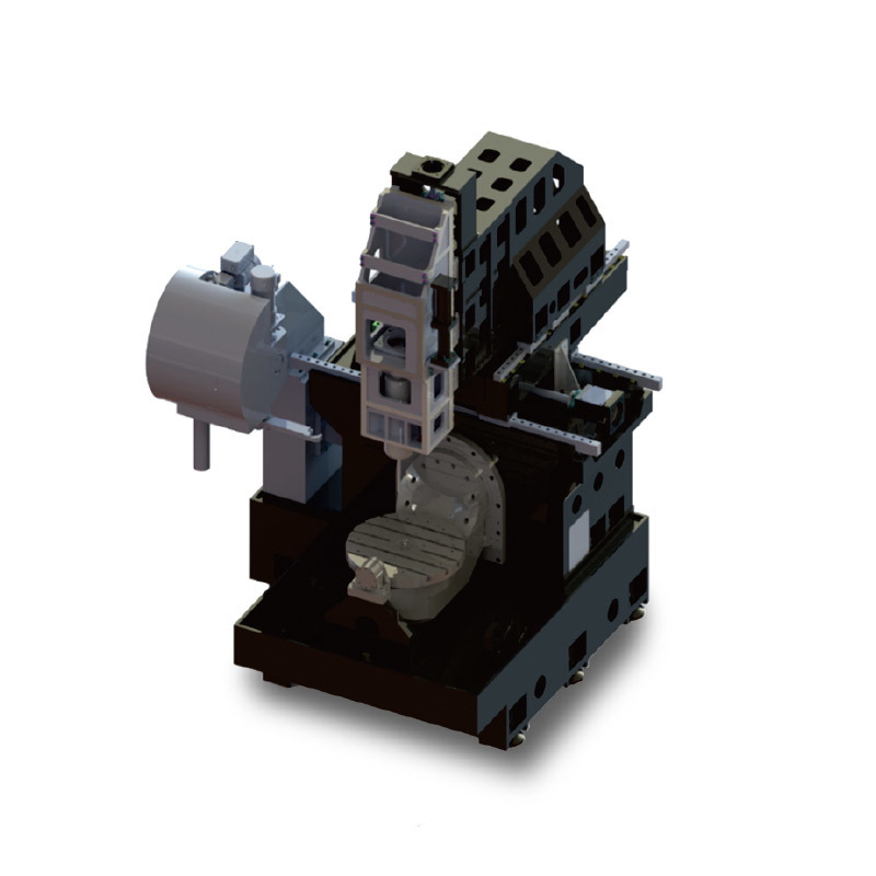
Index the rotary axes, lock the orientation, and machine with three linear axes when the feature is reachable from a fixed direction. This approach can simplify programming, reduce collision exposure, improve stability, and make inspection easier. It is often suitable for angled holes, side faces, local cavities, and finishing from several fixed directions.
Use simultaneous motion when the contact angle must change continuously
Continuous five-axis machining is useful for blended surfaces, steep and shallow transitions, complex cores, and features where maintaining an effective cutter contact point improves access or finish. The benefit depends on controller functions, postprocessor quality, kinematic calibration, CAM strategy, and the programmer's ability to manage rotary motion.
Build the Datum Strategy Around Mold Handoffs
Precision molds pass through roughing, stress relief, heat treatment where applicable, semi-finishing, finishing, drilling, EDM, polishing, fitting, and inspection. The datum plan must survive these handoffs. Identify permanent references, sacrificial features, probing locations, stock allowances, and how the part will be recovered after removal.
For every setup, define how the coordinate system is established, how rotary-center errors are controlled, and how the mold will be inspected in the same reference system. Setup reduction is valuable only when it also reduces datum uncertainty.
Control Tool Reach Before Chasing Spindle Speed
Short tools are one of the strongest reasons to use multiple orientations. Calculate holder clearance, gauge length, flute length, neck diameter, corner reach, and remaining stock. Simulate the holder and spindle nose, not only the cutting tool. Then check whether the selected orientation creates poor chip flow, trapped coolant, or contact conditions that shorten tool life.
Connect CAM, Postprocessing, and Machine Kinematics
A capable machine can still produce poor results when the digital chain is not controlled. A 5 axis machining center for precision molds depends on an accurate machine model, calibrated kinematics, and a proven postprocessor. Confirm rotary limits, pivot definitions, axis direction, unwinding behavior, feed interpretation, controller options, postprocessor ownership, simulation method, and revision control. Define who proves the postprocessor and what happens when software, controller parameters, or machine configuration changes.
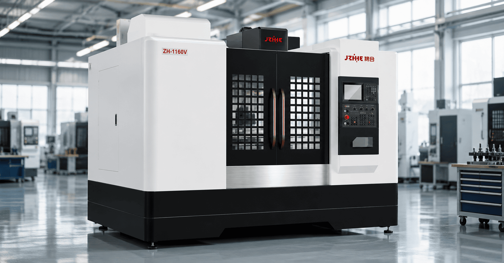
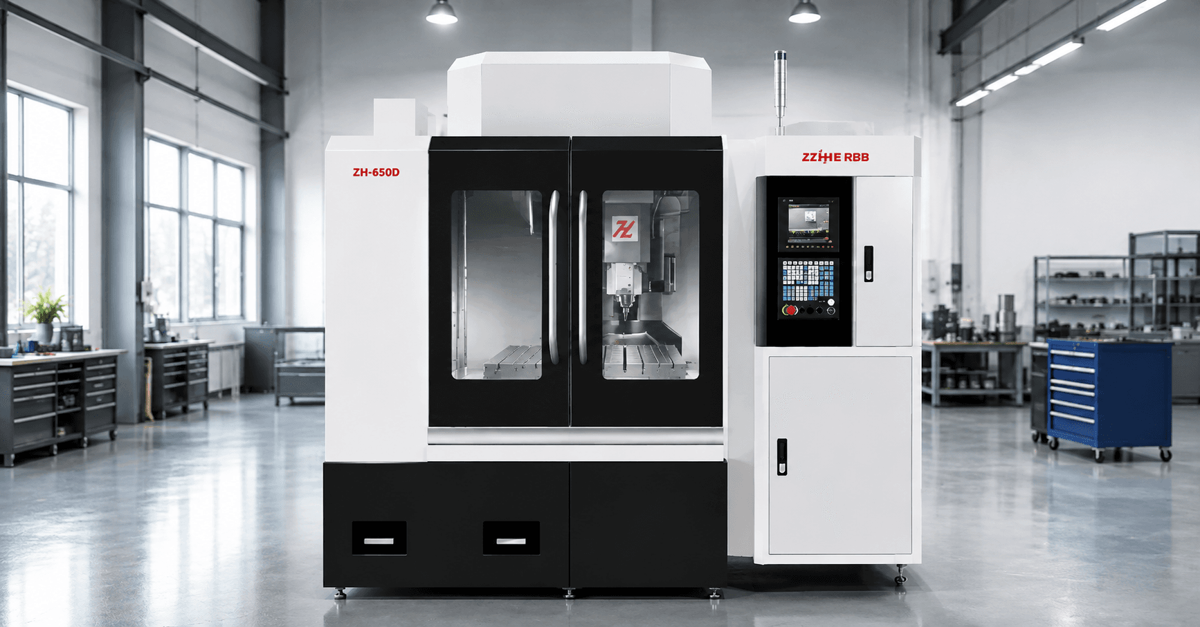
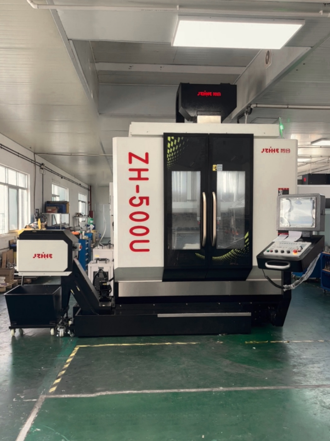
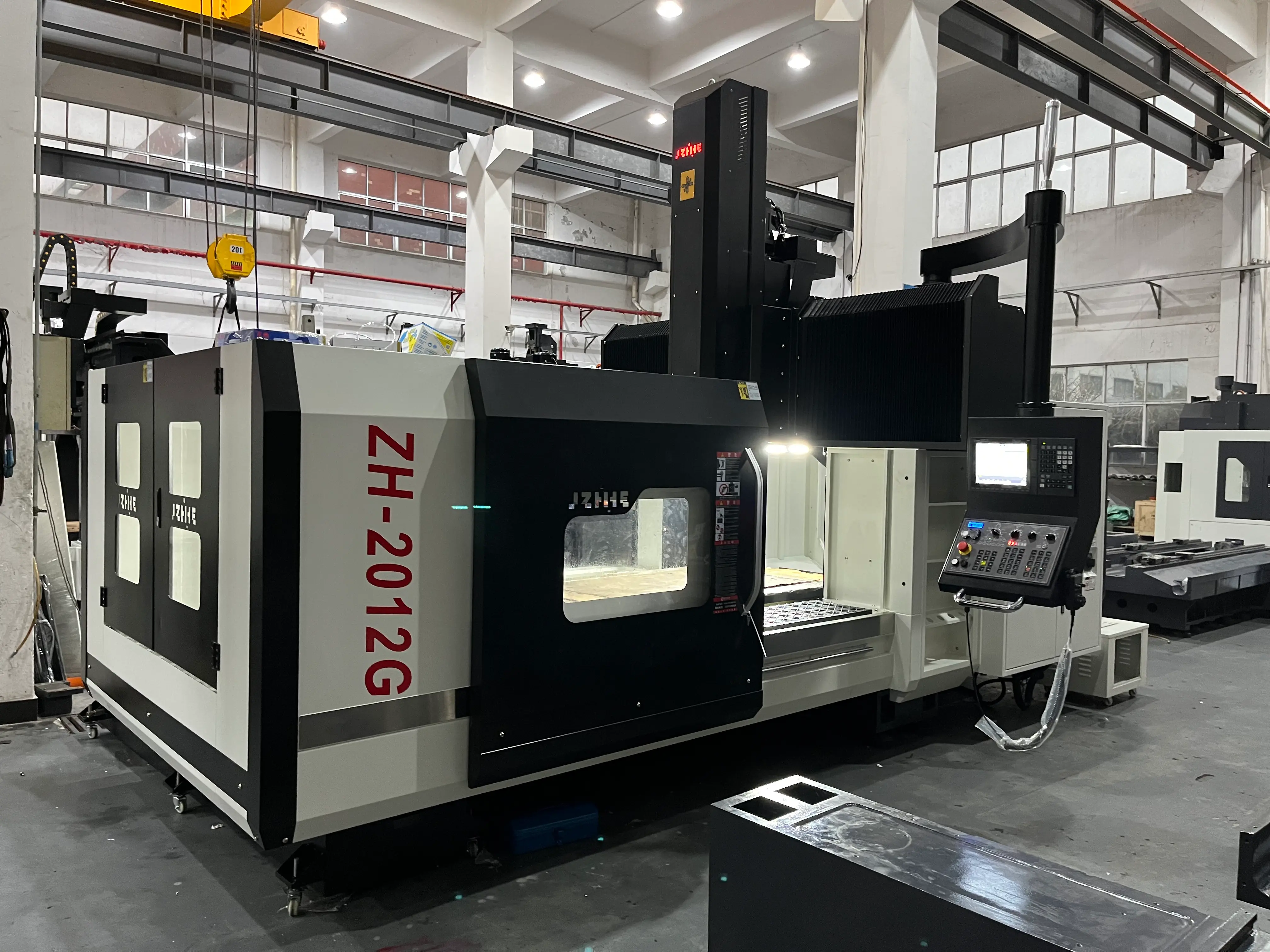
Zhihe CNC describes its five-axis machining center as a compact platform with a high-speed spindle, precision capability, and stability for complex parts, including mold work. Buyers should validate those general capabilities using their own CAM output, tool assembly, mold material, and inspection plan. The five-axis product category provides the starting point for model review.
Use a Three-Stage Mold Acceptance Part
- Access stage: Machine angled holes, steep walls, deep ribs, and a representative undercut to prove reach and collision control.
- Surface stage: Include shallow-to-steep transitions, fillets, blends, and adjacent patches to expose tool marks and rotary-motion behavior.
- Geometry stage: Measure datums, hole positions, profiles, flatness, and transition regions after the part returns to a stable temperature.
Record program version, postprocessor version, tooling, offsets, calibration state, cycle segments, interventions, and inspection results. If polishing is required, measure the polishing allowance and time rather than accepting a subjective statement that the surface “looks good.”
FAQ
Does every precision mold need simultaneous five-axis machining?
No. Many features are more efficiently produced with three-axis or indexed 3+2 machining. Use simultaneous motion where continuous orientation creates measurable access, finish, or setup value.
What is the biggest hidden implementation risk?
The digital chain is frequently underestimated. CAM data, machine kinematics, postprocessing, simulation, controller options, and calibration must work as one controlled system.
Should the acceptance test use hardened material?
Use material and condition representative of the production risk. If hardened finishing is critical, the test should reproduce that condition or clearly state the limitation.
How should surface quality be accepted?
Define measurable roughness where appropriate, visual inspection conditions, allowed witness marks, blending zones, polishing allowance, and the inspection method before the trial.
Request a Mold Feature Routing Review
To evaluate a 5 axis machining center for precision molds, provide mold dimensions, material and hardness, feature map, tool-reach concerns, CAM system, postprocessor status, tolerances, finish targets, inspection method, and production schedule. Use the Zhihe CNC contact page to request a model, process, and trial recommendation.