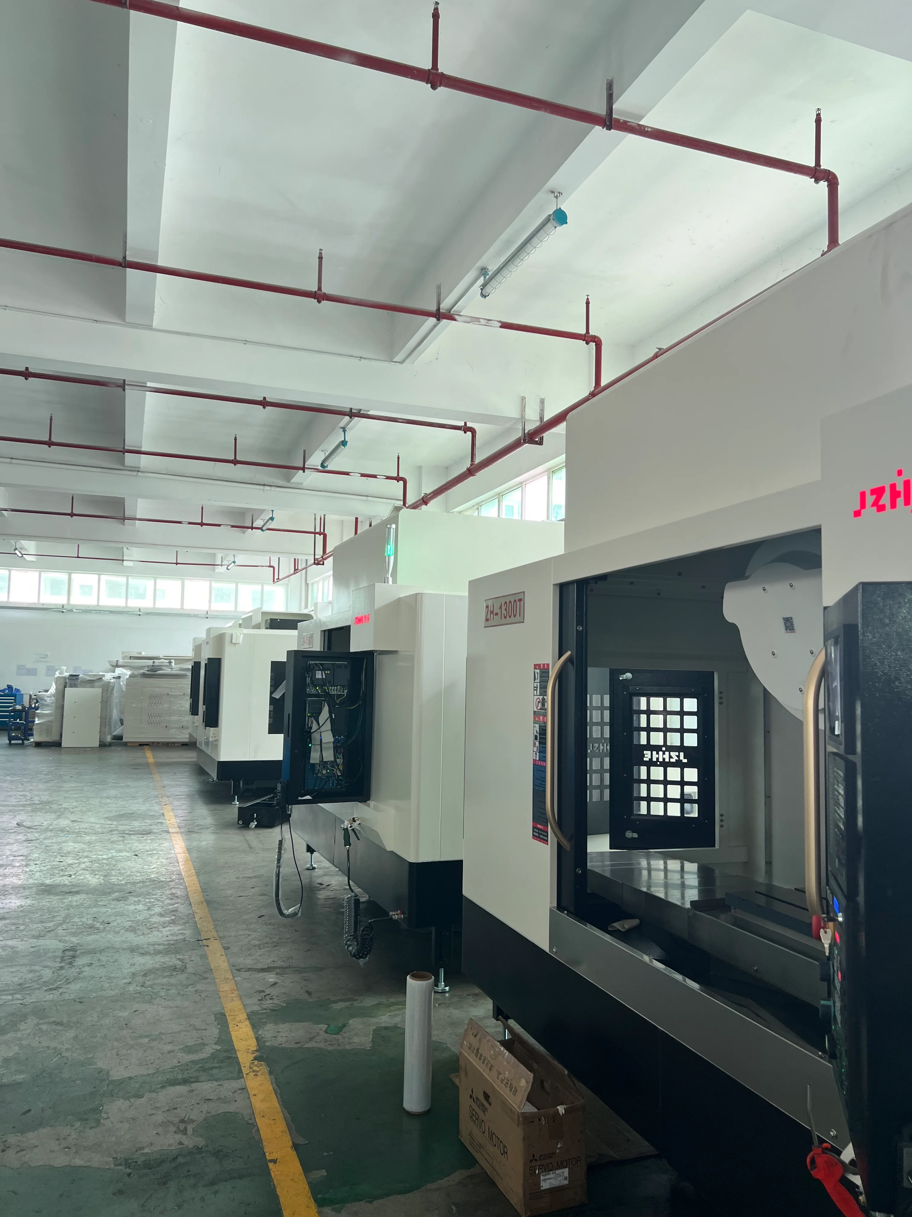
CNC drilling and tapping center thread quality is a process result, not a number printed on a tap package. A good thread depends on the material, hole preparation, tool geometry, synchronization, coolant, chip evacuation, clamping, inspection method, and the decision made when the first piece is not right. Buyers and production teams should agree on that chain before they compare cycle time.
This guide is for process engineers, quality engineers, production supervisors, and buyers evaluating a drilling and tapping center for repeated threaded features. It is a control-plan approach rather than a universal cutting-parameter sheet. Final speeds, feeds, tools, lubricants, guarding, and inspection limits must be validated for the actual material, drawing, machine, and destination requirements.
Define the Thread as a Release Condition
Start with the drawing and separate the requirements that are often bundled under “thread quality.” Record thread standard, size, pitch, class or tolerance, depth, incomplete-thread allowance, entry condition, bottom form, surface treatment, and the functional part that will mate with it. A cosmetic thread and a pressure-boundary thread need different evidence.
Add the inspection state. Is the thread checked in the machine, with a plug gauge, with a mating fastener, by measurement, or by a later leak or assembly test? Note whether the part is inspected clamped, warm, washed, deburred, or fully released. A result is difficult to interpret when the part state changes between machining and inspection.
The CNC drilling and tapping center thread quality record should identify the person who can release the feature and the person who can change the process. Those roles are often different, and leaving the boundary vague makes a small defect harder to contain.
For CNC drilling and tapping center thread quality, the first release question is not “Did the tap reach depth?” It is “Does the controlled thread accept the intended functional check without damage, contamination, or an unrecorded adjustment?”
Convert the Drawing Into a Thread Control Card
Create one row for every critical thread family. Keep the card short enough for an operator to use and detailed enough for engineering to trace.
| Control-card field | What to record | Why it matters |
|---|---|---|
| Thread identity | Standard, size, pitch, class, depth, and drawing revision | Prevents a correct process from being applied to the wrong feature |
| Hole preparation | Drill, bore, chamfer, pilot, and depth condition | Controls material left for the tap and entry damage |
| Tool state | Tap type, coating, holder, wear limit, and replacement rule | Separates tool deterioration from machine or material effects |
| Machine motion | Synchronization, spindle mode, feed relationship, and reversal behavior | Connects thread form to the actual control and tool path |
| Fluid and chips | Coolant or lubricant, delivery direction, concentration, and evacuation | Reduces heat, packing, galling, and false failures |
| Inspection | Gauge, mating part, measurement point, frequency, and acceptance rule | Makes release repeatable across shifts and operators |
| Response | Hold, clean, recheck, tool change, offset review, or engineering escalation | Stops local adjustments from hiding a systemic drift |
Use the card in the quotation review as well as on the shop floor. A supplier should know which thread features are representative, which are difficult, and which need a trial with production material.
Bring the CNC drilling and tapping center thread quality card into the machine comparison, because a fast cycle that cannot produce a traceable thread is not a useful production advantage.
Start With the Hole, Not the Tap
A tap cannot rescue an inconsistent hole. Check drill diameter, hole straightness, entry chamfer, depth, burr condition, and the relationship between the hole axis and the part datum. A hole that is too small increases torque and can damage the tap. A hole that is too large may produce a weak or incomplete thread. A damaged entry can make a functional gauge fail even when the internal form is acceptable.
For blind holes, confirm the usable depth after the drill point, chip space, tap lead, and required full-thread length are accounted for. A nominal depth can look adequate on a drawing while leaving no safe margin for chips or the tap's non-cutting section. Record the bottom condition and inspect it when the application depends on full engagement.
Material variation belongs on the same review. Aluminum, stainless steel, cast iron, and difficult alloys do not present the same cutting behavior. Hard spots, cast skin, smeared material, or residual stress can change the result from one blank to the next. Separate material evidence from machine evidence before changing offsets.
The NIST discussion of a flexible fixturing system is useful background when a thin housing or an eccentric blank may move under clamping. It does not replace a trial on the proposed part.
Match Tool Geometry to the Job
Choose the tap, drill, holder, and chamfer tool as a set. Review flute form, point style, coating, relief, reach, coolant delivery, and whether the tap is intended for through holes or blind holes. A long tool may reach the feature but lose stiffness or increase deflection. A tool that is excellent in a free-cutting alloy may struggle when the material work-hardens.
Define a tool-life rule that the operator can observe. It might be thread gauge torque, a measured feature trend, a maximum hole count, edge damage, or a combination. Do not wait for a broken tap to declare the tool exhausted. The CNC machine toolholder maintenance guide is a useful reminder that holder condition, runout, and clamping surfaces are part of the cutting system.
CNC drilling and tapping center thread quality improves when tool changes are triggered by evidence rather than by a vague statement such as “replace when the finish looks poor.” Keep the trigger, the observed value, and the person who owns the decision on the control card.
Verify Synchronization and Chip Evacuation
Rigid tapping depends on the relationship between spindle rotation and axial feed. Review the control mode, pitch calculation, spindle response, reversal, and any setting that changes the behavior at the bottom of the hole. The machine supplier should confirm the ordered configuration and the control functions used by the proposed program.
Then review the chip path. Chips can pack in a blind hole, wrap around a tool, block coolant, or scratch the thread during withdrawal. Include the actual hole depth, material, tap style, coolant direction, and any peck or chip-breaking method in the trial. A clean-looking sample made with an unusual manual cleaning step is not representative evidence.
Use the drilling machining center product range and the release-gate guide for CNC drilling and tapping as starting points for machine and process questions. Ask which functions are standard, which are options, and which depend on the selected control and spindle package.
Control Coolant and Lubrication as Inputs
Record the fluid type, concentration or delivery setting, pressure, nozzle position, temperature, filtration, and replenishment method. A fluid that reaches the top of the part may not reach a blind thread. A concentration that is acceptable for drilling may not be appropriate for the tap, material, seal, or downstream washing process.
The CNC machine coolant system selection guide can help structure the interface discussion. Keep the thread control card specific to the operation. The important evidence is the fluid condition at the tool, the chip behavior, and the effect on the finished feature.
Inspect With a Functional Gauge and a Process Signal
Choose the primary inspection method according to the risk. A go gauge can show functional acceptance, but it may not explain a trend. A measurement system can show pitch or diameter, but it may not replicate assembly. A mating part can reveal fit but can also hide damage or contamination. Use more than one method when the thread is safety-critical, leak-critical, or expensive to repair.
Define gauge condition, cleaning method, insertion force, rotation rule, inspection temperature, and what happens after a failure. The CNC machine acceptance test guide is useful for separating configuration checks, safety functions, and representative machining evidence. Thread acceptance should be part of that evidence when threaded features are central to the job.
Track the result by tool, station, material lot, operator-relevant setup, and machining order. A sudden failure after a tool change suggests a different investigation from a gradual increase in gauge torque across a batch. The data does not diagnose the cause automatically, but it tells the team where to look first.
Separate Machine, Tool, Material, and Method Signals
When a thread fails, resist the fastest explanation. Use a four-column review:
| Signal | Questions to ask first | Useful confirmation |
|---|---|---|
| Machine | Did synchronization, spindle response, zero return, or runout change? | Known-good tool and reference material on the same machine |
| Tool | Is the tap worn, chipped, loaded, misidentified, or incorrectly clamped? | New tool comparison and holder/runout check |
| Material | Did hardness, cast skin, temper, lot, or blank condition change? | Material record and a controlled sample from another lot |
| Method | Did the hole size, chamfer, coolant, depth, program, or cleaning step change? | Revision review and a repeat cycle with one controlled change |
This is more reliable than adding spindle speed or feed to every failure. A change can improve one sample while moving the process farther from a stable window. Close the investigation with a documented cause, correction, and re-verification.
Run a First-Piece and Repeat-Piece Plan
For each phase, record:
- The thread identity, material lot, tool, holder, program revision, and machine configuration.
- Hole and tap preparation, fluid condition, and chip-clearing method.
- Gauge result, mating-part result where applicable, and any measured trend.
- The decision to release, hold, rework, change the tool, or escalate.
For CNC drilling and tapping center thread quality, the repeat-piece plan should include the worst representative thread, not only the easiest feature. If the process is intended for unattended production, test the alarm, tool-change, missing-part, and recovery conditions that matter when no engineer is standing beside the machine.
Protect the Operator and the Machine
Thread failures can create sharp chips, broken tools, stored energy, and manual clearing tasks. The response procedure must define when the machine is stopped, isolated, and inspected. Do not ask an operator to reach into a guarded area to retrieve a broken tap or clear a packed hole.
OSHA's machine-guarding requirements discuss point-of-operation hazards, safeguarding, and control of access. Apply the laws and competent-person requirements of the destination market. A thread control plan is not a substitute for machine guarding, lockout, training, or risk assessment.
Example: One Good Thread Hides a Drift
Consider an aluminum housing with twelve blind threaded holes. The first part passes a go gauge. After a few dozen parts, two holes begin to show higher insertion torque. A quick offset change makes the next part pass, but the trend returns.
The team checks the record by tool and finds that the high-torque holes are on the same station. The hole drill is beginning to wear, the entry chamfer is smaller, and chips are collecting at the bottom because the coolant nozzle moved during cleaning. The tap is not the only problem. The corrected route restores the hole preparation, repositions the nozzle, sets a drill replacement trigger, and keeps the tap evidence separate from the hole evidence.
Questions From Production and Quality Teams
Can a good go gauge prove the thread is acceptable?
It can provide useful functional evidence, but it may not describe every requirement. Confirm the drawing, gauge class, cleaning method, insertion rule, and any assembly or leak test. Use additional measurement when the risk requires it.
Should the tap be changed whenever one thread fails?
Not automatically. Hold the affected pieces, verify the gauge and hole condition, review the program and synchronization, and inspect the tool and holder. Replace the tool according to an evidence-based rule, then re-verify with representative material.
Why can threads fail after drilling still looks normal?
Threading adds torque, synchronization, chip, lubrication, and tool-condition variables. A hole can look acceptable while being too small, misaligned, rough, deep in chips, or incorrectly chamfered for the tap.
Is rigid tapping always required?
The correct method depends on the machine control, spindle, tool, thread, material, and required result. Ask the supplier to confirm the ordered configuration and prove the representative feature rather than assuming a mode from a machine name.
How many parts should be included in the trial?
Enough to expose the variation relevant to the decision, including the hardest thread and the normal setup sequence. A single demonstration part is evidence of possibility, not proof of production stability.
What does CNC drilling and tapping center thread quality include beyond gauge fit?
It includes the drawing requirement, hole preparation, tool and holder condition, synchronization, coolant and chip behavior, inspection state, trend evidence, and the documented response to a failed feature. Gauge fit is one release signal, not the whole control plan.
What should be sent for a thread-quality review?
Send controlled drawings, thread standards, material and blank conditions, hole and chamfer details, tap and holder data, coolant information, inspection method, production volume, defect history, and the proposed machine and control configuration.
Send Zhihe CNC a Thread Evidence Pack
For CNC drilling and tapping center thread quality, send Zhihe CNC the thread control card, representative parts, drawing revisions, material records, tool and holder plan, coolant conditions, gauge method, production mix, and open trial questions. Ask for a model-specific review of spindle and control functions, tool access, chip evacuation, coolant interfaces, acceptance samples, and quotation exclusions. Use the Zhihe CNC product range to compare machine architectures, then contact the engineering team with the evidence pack.