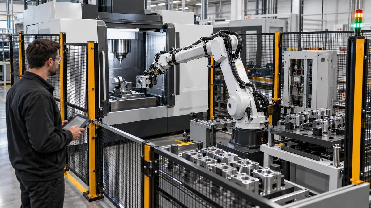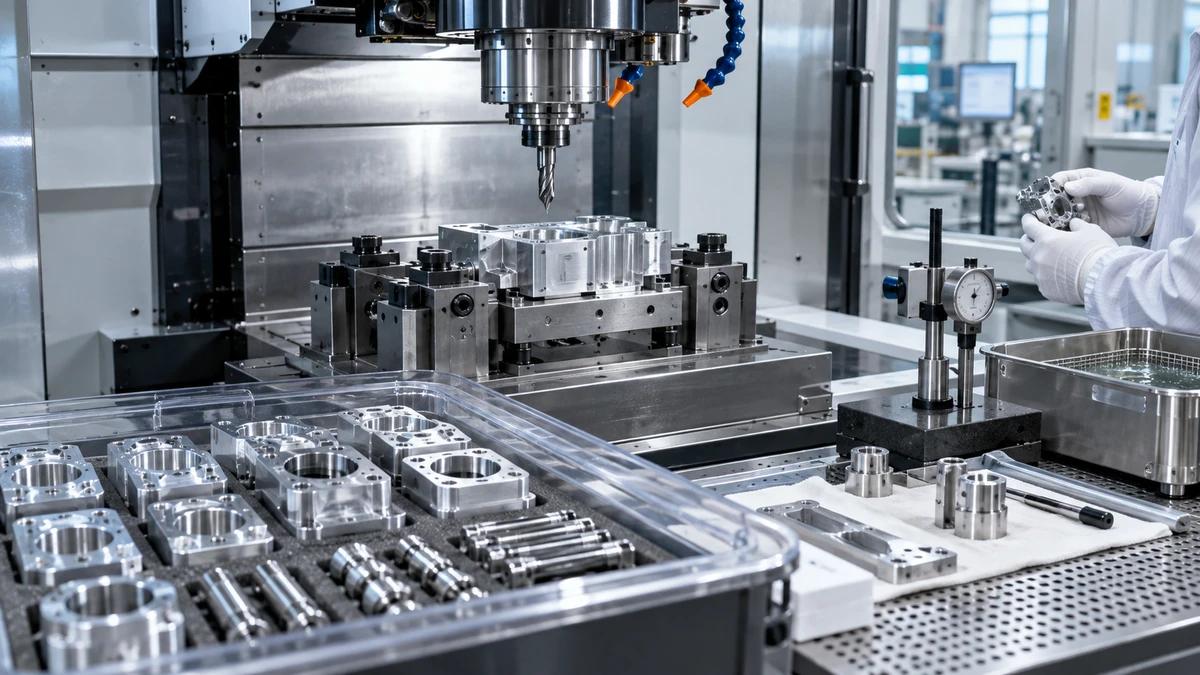
A CNC machine for communication equipment parts should be evaluated from the completed enclosure backward. A housing may pass dimensional inspection and still create trouble when the connector will not seat, the gasket loses compression, a heat-spreading interface rocks, or a coated joint no longer provides the intended contact. The machining route has to preserve the relationships that the final assembly actually uses.
This guide is for enclosure designers, process engineers, quality teams, and machine buyers working with radio, networking, antenna, edge-computing, or related hardware. Machining quality supports assembly and design intent, but it does not by itself establish electromagnetic compatibility, radio approval, environmental sealing, or regulatory compliance.
Open the Finished Assembly First
Before reviewing machine travel or spindle power, inspect the assembled product model and build sequence. Mark the interfaces that close the mechanical, thermal, electrical, and environmental paths. Typical examples include connector faces, gasket lands, cover joints, heat-source pads, shield contacts, mounting datums, antenna features, and cable exits.
Then identify which machined features control two or more interfaces. A connector bore may relate to a PCB mount, an external cutout, and a sealing face. A cover step may locate the lid while setting gasket compression. These relationships deserve priority in the process plan.
The CNC machine for communication equipment parts selection should follow that relationship map. Nominal axis travel alone says little about whether the critical faces can stay in one datum chain.
Translate Assembly Risk Into Machining Characteristics
Avoid giving every dimension equal weight. Build a short characteristic list that connects the drawing to a failure that matters.
| Assembly function | Machined characteristic to control | Downstream evidence |
|---|---|---|
| Connector alignment | Bore or cutout position to PCB and housing datums | Mating check and dimensional report |
| Gasket sealing | Land flatness, width, surface condition, step depth | Compression design review and leak test plan |
| Thermal transfer | Pad flatness, coplanarity, finish, fastener relationship | Interface fit and thermal validation |
| Shield or ground contact | Joint geometry and protected contact area | Assembly inspection and EMC validation plan |
| Cover installation | Hole pattern, counterbore depth, locating step | Torque sequence and fit check |
| Outdoor drainage | Slope, pocket floor, drain feature and orientation | Water-management review |
The machine trial should measure the machining characteristic. The product qualification plan should test the downstream function. Keep those claims separate.
Design a Datum Chain That Reaches the PCB
Communication enclosures often contain several coordinate systems: casting or extrusion stock, machined housing datums, PCB mounting points, connector bodies, cover geometry, and external rack or pole mounts. Draw how they connect.
If a connector hole is machined in a second setup, define what re-establishes its relationship to the PCB bosses. If cover holes are located from a cosmetic edge while the gasket land uses another datum, tolerance can accumulate across the joint. Use shared functional references where the design permits and inspect the relationship that assembly consumes.
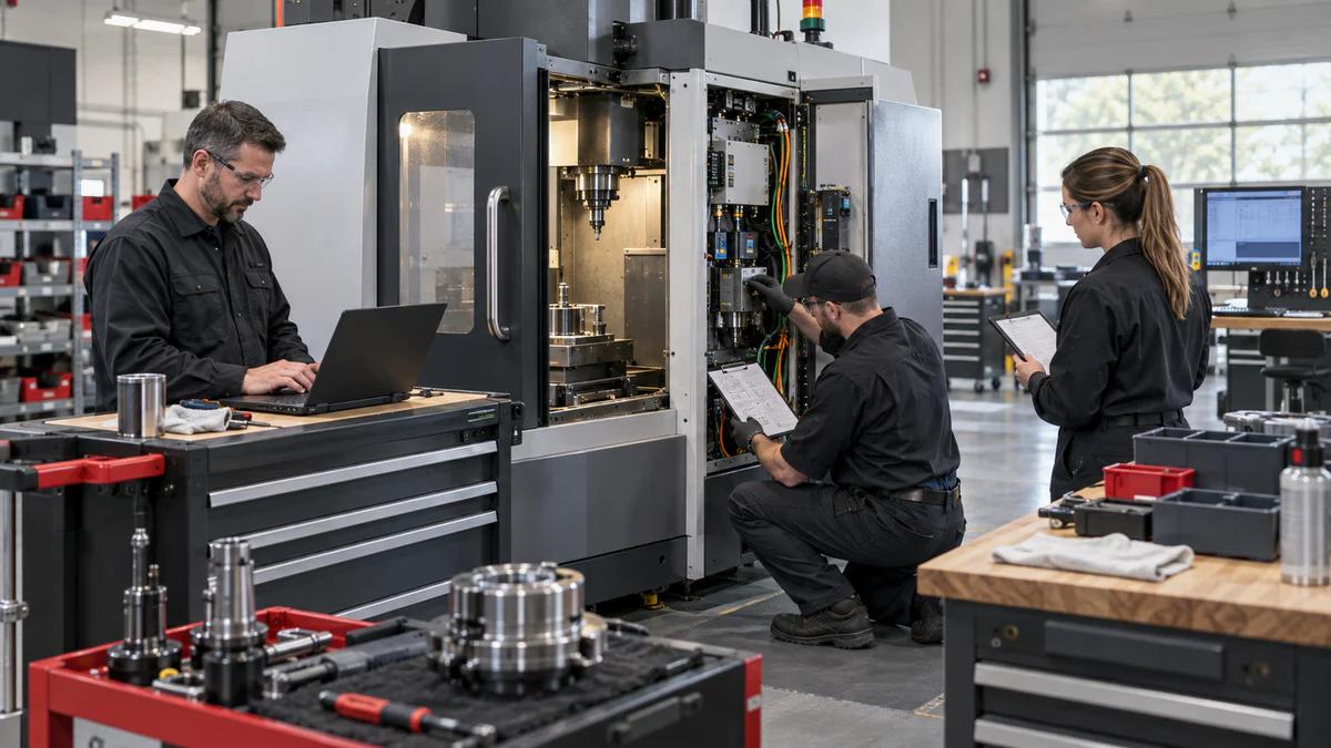
Probing may support setup control, but it cannot remove blank distortion or inconsistent seating. The probing system guide can help define when a measured datum may update an offset and when the process must stop.
Put Coating and Surface Treatment Into the CAD Review
Anodizing, conversion coating, painting, plating, blasting, and masking can change fit, edge condition, electrical contact, appearance, or measurement interpretation. Mark keep-out and contact regions explicitly. Decide whether dimensions apply before or after treatment and who verifies masked areas.
Threads, counterbores, connector seats, gasket lands, heat-transfer pads, and grounding locations may need different treatment rules. Do not let a general note such as "anodize after machining" carry all of that intent.
Run the pilot through the intended finishing route when finishing affects assembly. An as-machined sample cannot close a question created by coating buildup or masking variation.
Protect Sealing Geometry From Chips and Burrs
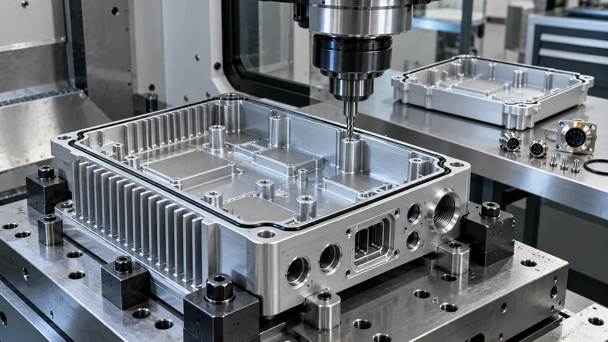
A small burr across a gasket land can matter more than a cosmetic tool mark elsewhere. Define protected surfaces during machining, cleaning, handling, deburring, and inspection. Specify how cross-holes, intersecting ports, threads, and pocket edges are checked for retained chips or sharp projections.
Chip evacuation needs particular attention in deep housings and ribbed pockets. Coolant delivery, tool path, fixture orientation, and cleaning access should be evaluated together. Review the CNC coolant system selection guide for system-level questions, then validate the actual enclosure geometry.
A CNC machine for communication equipment parts trial should include the full cleaning and deburring method. Manual finishing that is absent from the cycle estimate can become the largest source of variation at production volume.
Plan Thin-Wall Cutting Around the Released Shape
Large pockets and thin fins can release material stress, reduce stiffness, and move after unclamping. Record the blank route, roughing sequence, remaining stock, fixture support, clamp order, rest periods if used, finishing sequence, and released-part inspection state.
Measure both local features and global relationships. A wall can meet thickness while the connector face shifts relative to the board mount. If a vacuum, soft jaw, or expanding fixture is proposed, check how its force changes during roughing and whether it blocks chips or measurement access.
The process engineer should state what variation is controlled by machining and what requires a design, material, or blank-route decision.
Treat Thermal Pads as Interfaces, Not Isolated Flats
A machined pad may contact a heat spreader, module, or interface material. Its useful condition depends on flatness, coplanarity, finish, cleanliness, neighboring fasteners, and the assembled load path. A low roughness value alone cannot demonstrate thermal performance.
Identify whether several pads must share a plane and whether cover or board fastening distorts the housing. Control the surface through finishing and cleaning. Validate the thermal system under the product's actual design and operating conditions.
Do not claim that the CNC machine creates regulatory or thermal compliance. It creates a repeatable geometric input that the product team can validate.
Keep EMC Claims With the Product Qualification Team
Machined joints, contact lands, apertures, cover geometry, and connector placement can influence an enclosure's electromagnetic behavior. However, the outcome also depends on electronics, frequencies, cables, fasteners, coatings, gaskets, firmware, grounding, and the complete assembly.
The FCC's equipment authorization knowledge database is a source for U.S. authorization guidance. Its equipment authorization grantee registration data is a reference dataset, not proof that a machined enclosure or completed product is approved. Requirements differ by product and market, and qualified compliance professionals should determine the applicable route.
The machining record should state what geometry and surface condition were produced. The compliance file should state what finished product configuration was tested. Keeping the boundary clear prevents an accurate housing from being marketed as proof of compliance.
Select the Architecture From Setup Relationships
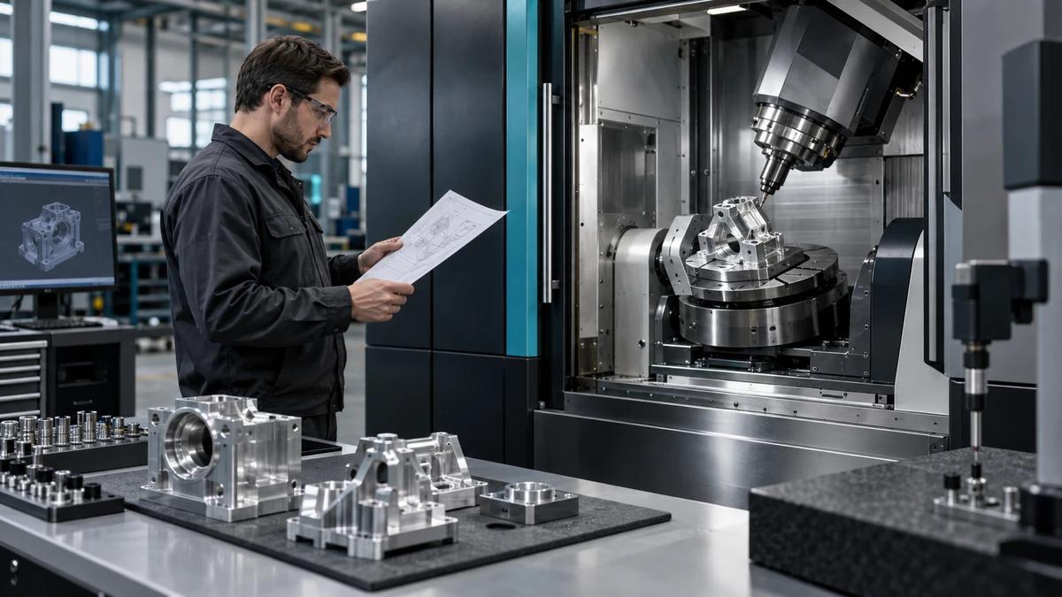
A vertical machining center may suit open housings, plates, heat sinks, and accessible prismatic work. A fourth-axis arrangement can preserve relationships across several sides. A five-axis machine may improve access or shorten tools for complex angled features. The correct architecture depends on the part, fixture, tool reach, production mix, and inspection strategy.
Compare usable work envelope after fixtures, rotary equipment, toolholders, probes, and guarding are included. Use the vertical machining center range, five-axis machining center range, and broader milling machining center range as starting points, then request model-specific data.
Build an Assembly-First Pilot
Select a representative housing and include the real cover, board or datum simulator, connector bodies, gasket or surrogate defined by engineering, and required fasteners. Run machining, deburring, cleaning, finishing, dimensional inspection, and assembly in the intended order.
Record setup references, tool assemblies, cycle interruptions, manual work, inspection results, coating state, and assembly findings. Repeat loading enough times to expose seating and handling variation. If a feature changes after finish or assembly, preserve the before-and-after evidence.
For CNC machine for communication equipment parts evaluation, the final review should include both a dimensional report and an interface report. One cannot substitute for the other.
Use a Process Gate for Every Interface Family
Different interfaces close at different stages, so one final inspection is inefficient.
| Gate | Verify now | Do not claim yet |
|---|---|---|
| After roughing | Stock, distortion trend, fixture stability | Final interface geometry |
| After finish machining | Datum relationships, pads, lands, holes, burr state | Coated fit or product compliance |
| After surface treatment | Masking, buildup-sensitive fits, contact regions | Complete sealing or EMC result |
| After assembly | Connector fit, cover seating, fastener access, gasket path | Environmental or radio approval without test |
| After qualification | Defined product tests on controlled configuration | Performance for untested variants |
Attach each gate to a drawing revision, part identity, method, result, and owner. This creates traceability when the enclosure, board, connector, or finish changes.
Prepare a Defect Escalation Map
Group defects by interface, not only by machining operation. A shifted connector cutout should trigger review of datum transfer, fixture seating, blank variation, board location, and measurement method. A leaking joint should trigger review of land geometry, burrs, coating, gasket, fasteners, assembly sequence, and test setup.
Give operators clear stop conditions and preserve failed parts before rework. Rework can remove the evidence needed to distinguish machining, finishing, and assembly causes.
Use serial or lot traceability for the machine program, fixture revision, tool state, material or blank batch, surface treatment batch, and assembly configuration when risk justifies it.
Write the RFQ From the Interface Map
Send the assembled CAD context, controlled part drawing, blank route, material, finishing and masking notes, annual mix, critical interface list, fixture constraints, inspection plan, and target acceptance sequence. State which test components the buyer will provide.
Ask the supplier to return a proposed machine configuration, setup and datum route, workholding concept, tool-access review, process boundary, measurement plan, manual operations, trial method, and quotation exclusions. A CNC machine for communication equipment parts quotation is useful only when its assumptions match the final assembly. Keep that assembly reference with later engineering changes, so the CNC machine for communication equipment parts plan does not drift away from product intent.
Questions Enclosure Teams Ask
Which features should be treated as critical first?
Start with features that connect multiple assembly functions: connector-to-board location, gasket lands, shared thermal planes, cover joints, grounding contacts, and mounting datums.
Does machining accuracy guarantee EMC performance?
No. Machining supplies geometric and surface inputs. EMC performance depends on the complete controlled product and must be validated under the applicable test and authorization route.
Should coating thickness be included in dimensions?
The drawing and process plan should state whether a dimension applies before or after treatment and which areas are masked or contacted. The answer depends on design intent and finish process.
How can thin-wall movement be reduced?
Review blank stress, stock distribution, roughing sequence, support, clamping, tool path, heat, intermediate conditioning, and released-state inspection. The effective combination is part-specific.
Is a five-axis machine always better for an enclosure?
No. It may improve access or reduce setups, but fixture complexity, envelope, programming, inspection, and production mix matter. Choose the architecture from required feature relationships.
What should the pilot include besides the machined housing?
Include relevant covers, board or simulators, connectors, gasket strategy, fasteners, surface treatment, cleaning, inspection, and the planned assembly sequence.
How should gasket lands be inspected?
Follow the drawing and sealing design. Typical controls may include geometry, width, flatness, surface condition, interruptions, burrs, coating, cleanliness, and relationship to fasteners.
Can probing correct casting or extrusion variation?
It can measure defined references and support controlled offsets. It cannot eliminate insufficient stock, distorted blanks, unstable seating, hidden defects, or an invalid datum strategy.
What evidence belongs with surface treatment?
Keep treatment specification, masking definition, batch traceability where required, visual and dimensional checks, protected contact areas, and before-and-after results for sensitive fits.
What should trigger a stop during production?
Define limits for datum seating, missing stock, burr or chip condition, critical dimensions, finish damage, tool state, fixture condition, and any interface result that cannot be corrected within the approved process.
Close the Loop at the Assembly Bench
To review a CNC machine for communication equipment parts application, send Zhihe CNC the enclosure and assembly context, interface map, controlled drawings, material and blank route, finish notes, inspection method, production mix, and pilot components. Use the product portfolio to shortlist architectures, then contact Zhihe CNC for a configuration and trial discussion grounded in the finished assembly rather than an isolated metal part.