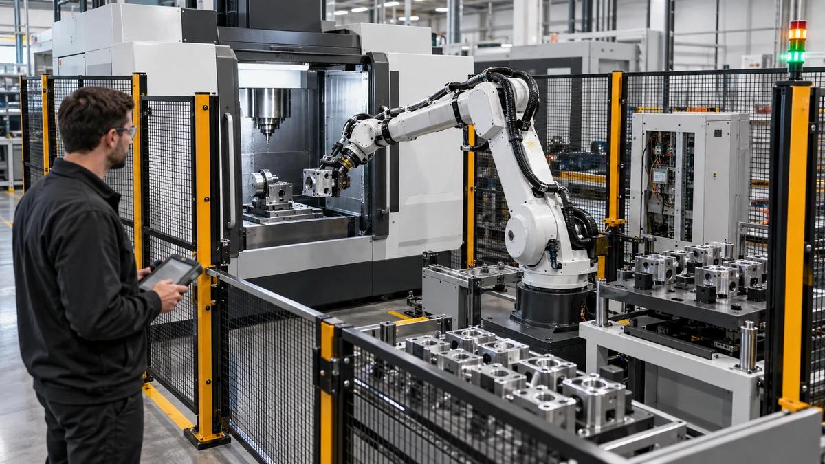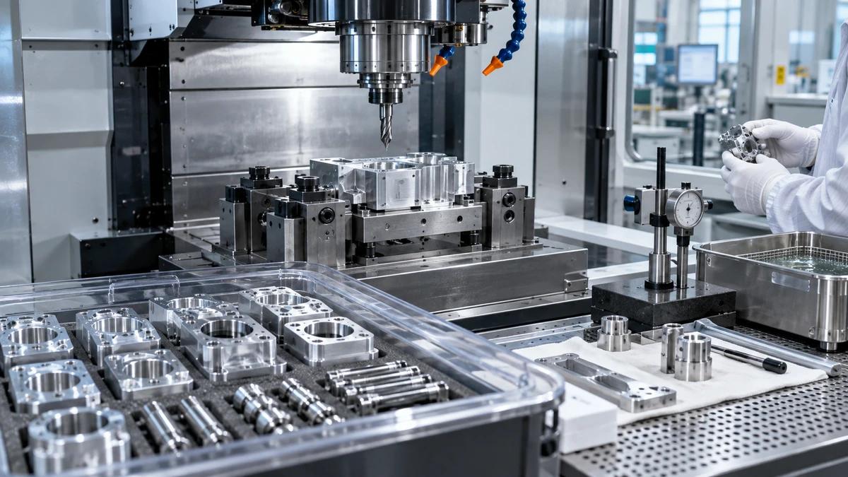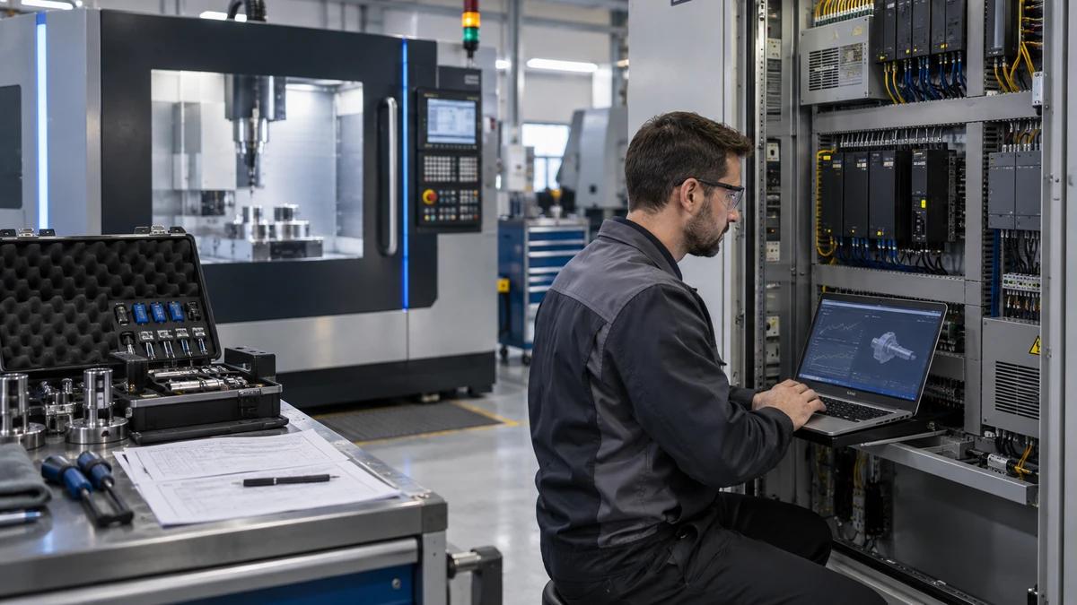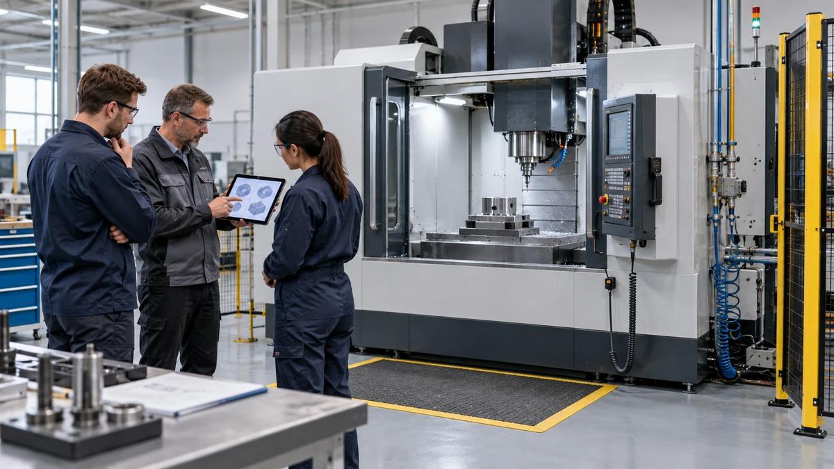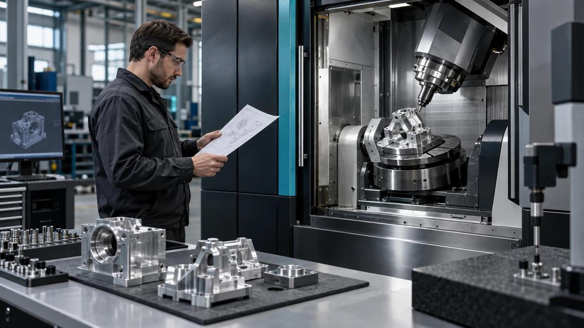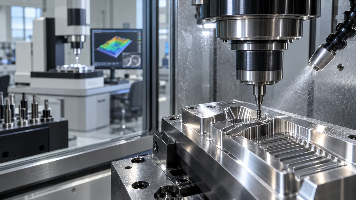
A precision engraving milling machine should be chosen with a measurement plan already beside the drawing. Small text, narrow ribs, optical transitions, electrode details, and fine channels can appear sharp under shop lighting yet fail their functional relationship. The buying decision becomes clearer when the team budgets error from datum to toolpath to released measurement instead of asking whether a machine is simply "high precision."
This guide is for mold, electrode, electronics, medical-component, and fine-detail teams planning a machine trial or RFQ. It offers a metrology framework, not guaranteed capability figures. Results depend on the ordered machine, process, environment, tooling, workholding, material, geometry, and inspection method.
Put the Functional Feature at the Center
Begin with the micro-feature that can reject the part. It may be channel width at a specified depth, edge position relative to a datum, local surface texture, corner form, wall thickness, draft transition, or an engraved character that must remain legible after coating.
Describe why the feature matters. A channel may control flow, an electrode corner may influence a later EDM result, and a mold insert transition may affect release or appearance. That function determines where to measure, how to filter data, and whether an average hides a local defect.
For a precision engraving milling machine review, keep the feature definition independent from the supplier's preferred demonstration. The test should challenge the buyer's actual relationship, not only reproduce an attractive sample.
Build a Measurement Budget Before a Machine Budget
List every step between the drawing and the reported value: datum establishment, blank condition, fixture seating, tool measurement, machine motion, thermal state, cutting force, burr formation, cleaning, part release, fixturing for inspection, instrument behavior, sampling, filtering, and result calculation.
Do not assign invented numbers where evidence is absent. Mark each contributor as estimated, measured, supplier-stated, or unknown. Then identify the few contributors likely to consume most of the tolerance or uncertainty budget.
NIST's surface and interface metrology program illustrates why measurement scale, instrumentation, and surface definition matter. A machine trial still requires a method designed for the specific feature.
Match the Instrument to the Question
Different instruments answer different questions. A touch probe may locate a robust datum but miss a fragile narrow feature. Optical systems can collect dense data yet remain sensitive to reflectivity, edge interpretation, focus, and filtering. Surface instruments may report texture over a defined trace or area without proving feature position.
| Feature question | Possible measurement approach | Method detail to lock |
|---|---|---|
| Position from datum | CMM, vision, or qualified in-process probing | Datum simulation, stylus or optical edge rule |
| Narrow channel width | Calibrated vision or optical profiler | Depth plane, threshold, lighting, sampling locations |
| Local surface texture | Contact or optical surface metrology | Cutoff, filter, direction, evaluation length or area |
| Corner or radius form | Profile scan, replica, microscopy, or section method | Fitting rule, magnification, preparation, uncertainty |
| Engraving legibility | Defined visual test plus dimensional checks | Viewing condition, minimum strokes, post-process state |
| Thin wall relationship | CMM, scanning, or purpose-built gauge | Clamping force, released state, temperature |
Choose the approach with the quality or metrology team before cutting. If the supplier and buyer use different edge definitions, both can measure carefully and still disagree.
Establish Datums Without Hiding Distortion
A small feature may be accurate relative to the local cut surface but misplaced relative to the part's functional datum. Reproduce the drawing datum scheme in manufacturing and inspection wherever practical. State when a substitute reference is necessary and how it affects interpretation.
Check what happens after the part leaves the fixture. A thin insert, foil-like wall, or stressed blank can move when released. Record whether results are measured clamped, supported, free-state, or after a conditioning period.
The CNC machining center probing system guide can help frame datum and offset questions. Probing is useful only when the probe, reference, update rule, and stop limit are defined.
Design the Trial Coupon Around Failure Modes
A good coupon is not a logo. Include features that expose tool runout, interpolation, edge quality, depth control, corner behavior, tool access, chip evacuation, and thermal sequence. Place repeated features at different table positions if working-envelope behavior matters.
Use the intended material and a representative blank preparation. Include at least one feature near the demanding size or aspect ratio, but avoid a coupon that is impossible to inspect reliably. Measurement access belongs in the coupon design.
For precision engraving milling machine comparison, use the same controlled geometry, stock, tool type, inspection method, and decision rules across candidates. Supplier-specific feeds and speeds may differ, but every difference should be recorded with the result.
Treat the Cutting Tool as a Measured Component
At micro-feature scale, nominal tool diameter is not enough. Record tool identity, measured runout, edge condition, gauge length, holder, coating, flute geometry, and the method used to establish size or length. Note whether the tool was new, conditioned, or reused.
Tool deflection and wear can change width, taper, floor finish, and edge shape through the path. Plan intermediate checks based on risk rather than assuming one tool state for the full coupon. A broken or damaged edge can leave a locally plausible surface while changing the functional geometry.
Keep tool inspection images with scale, lighting condition, and feature location. Unlabeled macro photographs are helpful for discussion but weak as release evidence.
Control Heat, Chips, and Cleanliness as Measurement Inputs
Machine warm-up, spindle behavior, coolant state, room temperature, material temperature, cutting sequence, and dwell can change a fine-detail result. Record the conditions that matter to the trial and repeat them when comparing runs.
Fine chips can recut a surface or pack a narrow channel. Coolant or air delivery can improve evacuation but may also deflect a small tool or influence thermal state. The CNC coolant system selection guide provides broader process questions; the trial must confirm delivery for the actual enclosure, tool, and geometry.
Clean the feature with an approved method before inspection. Aggressive brushing, blasting, or manual deburring can alter the very edge being measured. Record the inspection state: as-cut, cleaned, deburred, coated, or assembled.
Separate Machine Behavior From Process Behavior
When a result misses, sort evidence before adjusting parameters. Machine geometry, spindle behavior, servo response, toolholder condition, cutting parameters, tool wear, fixture compliance, blank stress, temperature, and measurement method can create similar symptoms.
Use diagnostic cuts and repeated measurements to isolate contributors. A machine calibration record is valuable, but it does not automatically predict a particular micro-feature. Conversely, one poor tool choice should not become a conclusion about the whole machine.
NIST's paper on dimensional metrology for micro- and mesoscale manufacturing provides useful technical context on scale-dependent measurement challenges.
Define an Inspection Sequence That Others Can Repeat
Write the sequence as if another laboratory will reproduce it. Include cleaning, conditioning, fixturing, datum alignment, instrument setup, calibration or verification status, feature locations, scan or point pattern, filter settings, fitting rule, repeat count, and reporting format.
Blindly collecting more points does not guarantee a better answer. Points must represent the feature and avoid invalid regions. Keep raw data and processed output so a filter or fitting choice can be reviewed later.
For a precision engraving milling machine pilot, measure selected features more than once, preferably with removal and replacement when fixturing repeatability matters. If practical, compare a subset by a second method to reveal systematic disagreement.
Use a Release Matrix Instead of One Pass/Fail Stamp
A single green cell can hide a weak measurement chain. Separate function, geometry, surface, edge, repeatability, process stability, and inspectability.
| Release dimension | Evidence to review | Possible decision |
|---|---|---|
| Functional geometry | Datum-related dimensions on representative features | Accept, adjust process, redesign route |
| Local form | Profiles, corners, tapers, channel floors | Accept or isolate tool/path issue |
| Surface condition | Defined texture data and defect map | Accept by function or revise finishing |
| Edge integrity | Burr, chipping, rollover, post-process effect | Modify tool, path, handling, or deburr |
| Repeatability | Repeated loads, cuts, and measurements | Expand trial or control seating/temperature |
| Measurement confidence | Method agreement, uncertainty, raw-data review | Accept method or escalate metrology study |
State whether a result is conforming, informative only, or unresolved. That label prevents an exploratory microscope image from becoming formal acceptance evidence.
Audit the Production Measurement Burden
A laboratory method may be too slow, delicate, or expensive for production. Decide which features need full inspection, sampling, in-process control, a functional gauge, or periodic laboratory verification. Include cleaning, fixturing, programming, analysis, and reporting time in the plan.
Confirm that the production team can access the necessary artifacts: master program, instrument recipe, calibrated standards, sample images, acceptance limits, and escalation route. A precision engraving milling machine process is not ready for routine release if only one specialist understands the result.
Write the RFQ Around Evidence Packages
Send controlled CAD and drawings, material and blank details, critical feature list, datum scheme, intended surface state, planned instrument, output assumptions, tool constraints, and sample quantity. Ask the supplier to identify machine configuration, process ownership, test environment, measurement method, exclusions, and raw evidence delivered.
Use the milling machining center range and vertical machining center range to compare architecture only after the feature and inspection needs are clear.
Questions Metrology and Process Teams Ask
What should a precision engraving milling machine trial prove?
It should demonstrate the defined feature relationships, surface and edge condition, repeat behavior, process inputs, and measurement confidence for a representative configuration and material.
Is visual sharpness a valid acceptance criterion?
It can be one defined criterion for appearance or legibility, but it should specify lighting, magnification, viewing distance, reference sample, and defect limits. It does not replace dimensional evidence.
How small a feature can the machine cut?
There is no responsible universal answer. Capability depends on geometry, material, tool, runout, access, cutting conditions, thermal state, machine configuration, and how the result is measured.
Why do optical and contact results disagree?
They may use different edge, filter, fitting, force, sampling, or surface-response definitions. Review the raw data and method before treating either number as the truth.
Should measurements be taken in the fixture?
Measure in the state relevant to function and drawing requirements. For distortion-sensitive parts, comparing clamped and released states may be necessary to explain movement.
Can a machine probe inspect micro-features?
Only when the probe system, stylus, access, uncertainty, and feature geometry support the task. Often it is better suited to robust datums or process checks than to the smallest feature.
How should tool wear be included?
Define the inspection interval, wear indicator, correction rule, replacement limit, and affected features. Keep the tool state with every measured result.
What environmental data should be recorded?
Record the conditions that could affect the decision, such as machine warm-up, room and part temperature, coolant state, spindle history, and time between cutting and measurement.
How many repeated measurements are enough?
Choose repeats based on risk, method variation, part value, and the decision being made. Include removal and replacement when fixturing contributes uncertainty.
What belongs in the final measurement package?
Include drawing revision, feature definitions, datum method, instrument and status, program or recipe, raw data, processing settings, results, images with scale, conditions, deviations, and approvals.
Make Measurement Part of the Machine Decision
When reviewing a precision engraving milling machine with Zhihe CNC, provide the micro-feature map, controlled geometry, material, tool constraints, datum logic, surface state, inspection method, and intended production rate. Explore the Zhihe CNC product portfolio, then contact the engineering team to define a trial whose data can survive technical review. The right outcome is a measured process boundary, not an unsupported precision label.