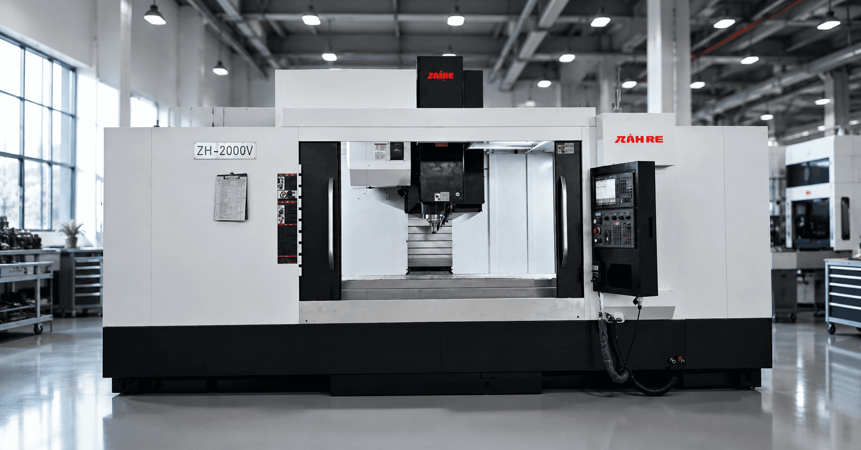
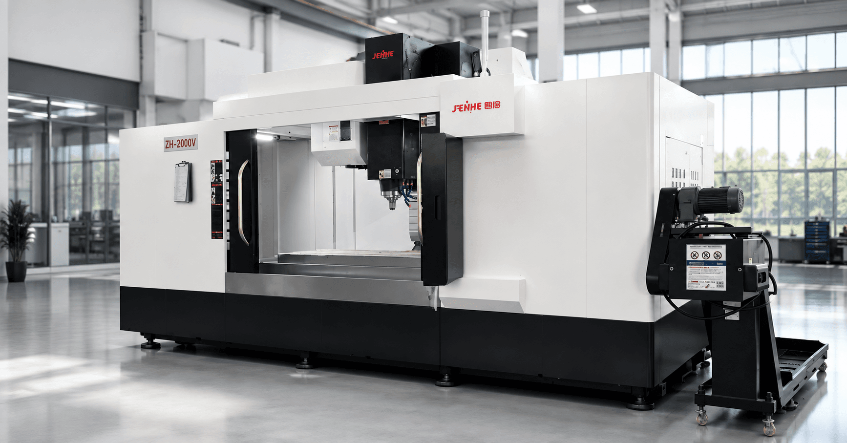
Titanium makes five-axis buying decisions less forgiving because the process must control force, heat, tool engagement, reach, and expensive material at the same time. Complex aerospace, medical, energy, and precision structural parts may benefit from one-setup access, but five-axis motion alone does not guarantee a stable titanium process.
A suitable 5 axis machining center for titanium must combine structural rigidity, usable spindle torque, a practical rotary envelope, short and stable tools, effective coolant and chip control, reliable calibration, proven CAM and post-processing, and a fixture that supports the part without blocking access.
This guide focuses on the evidence a buyer should request before accepting a proposal.
5 Axis Machining Center for Titanium: Prove the Difficult Feature and Longest Cut
Choose the machine around the hardest repeatable operation, not the most impressive simultaneous motion demonstration. Ask the supplier to machine the titanium grade, feature, tool reach, and surface that create the commercial risk. Record cycle time, spindle load, intervention, tool wear, measurements, and remaining limitations.
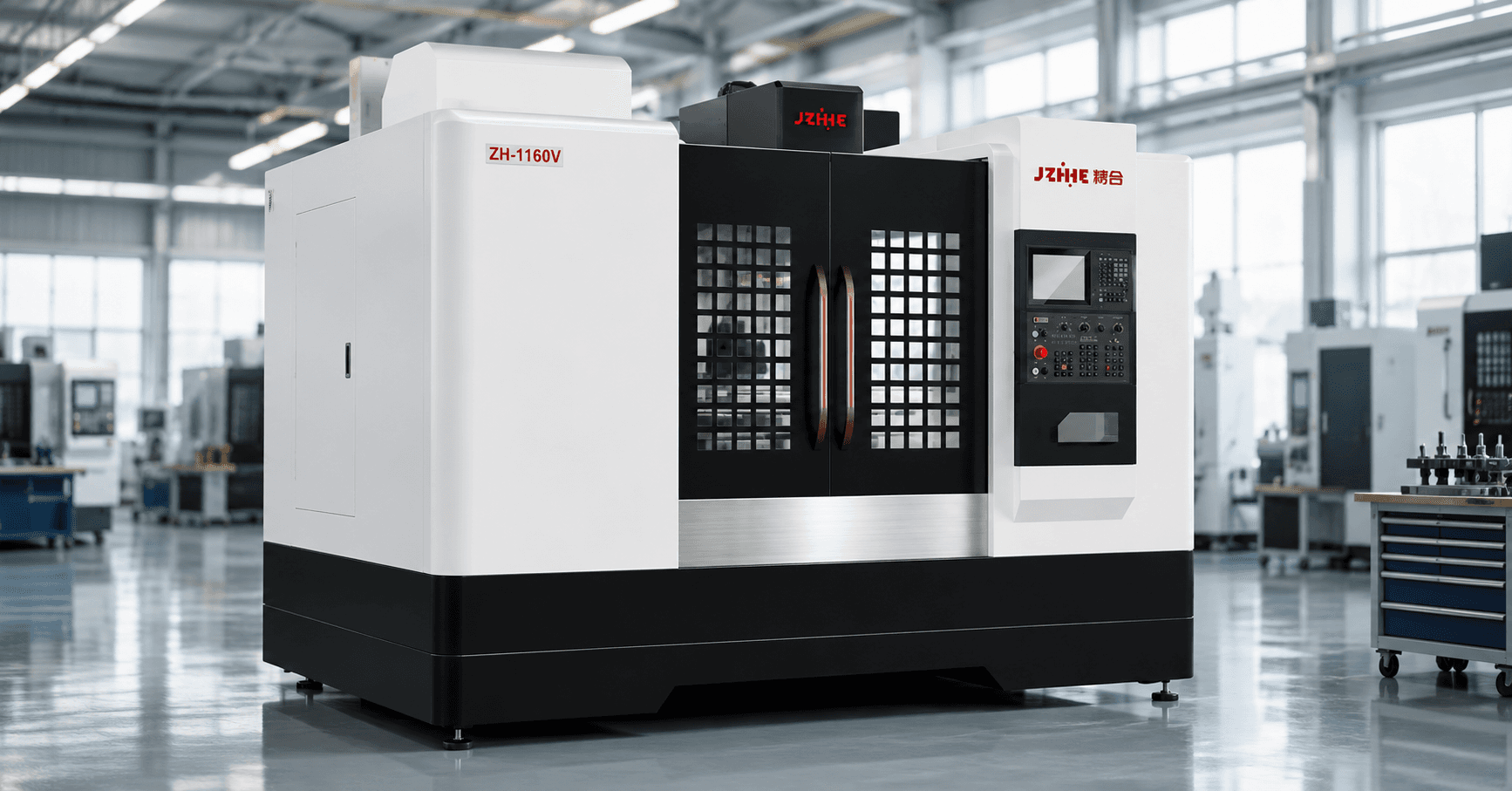
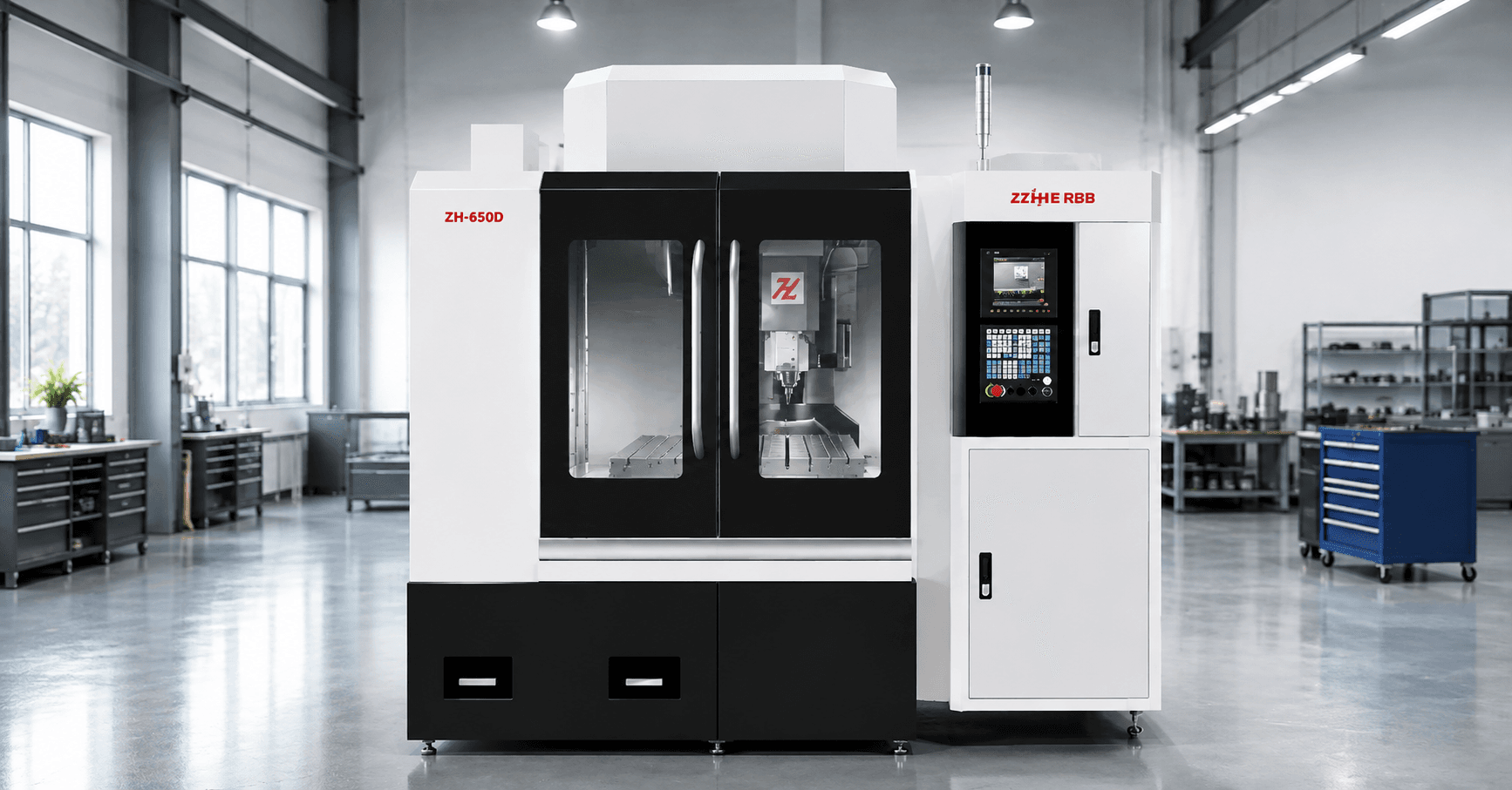
Zhihe CNC positions its five-axis machining center series for complex curved surfaces, aerospace parts, medical parts, and high-precision components. Its published project information also references titanium-alloy and stainless-steel structural parts. Those claims should be connected to the exact machine and process offered to the buyer.
Why Titanium Changes the Machine Discussion
Titanium alloys are grouped in ISO S with heat-resistant superalloys. Sandvik Coromant's ISO S material guidance emphasizes demanding heat and tool-life conditions. For the machine buyer, the practical consequences are stable engagement, controlled heat, reliable coolant delivery, and sufficient rigidity when tools become long or features become deep.
Common risks include:
- Heat concentrated near the cutting edge.
- High cutting forces relative to thin walls or slender features.
- Tool wear that changes dimensions during a long cycle.
- Vibration from overhang, weak support, or unstable engagement.
- Chip accumulation around deep pockets and fixtures.
- High material value that makes scrap and rework expensive.
The process does not need to be slow, but it needs a predictable operating window. Rapid traverse and headline rpm cannot compensate for a cut that chatters or overheats.
Map the Part, Stock, and Removal Strategy
Before comparing machines, document the titanium grade, stock condition, billet or forging size, finished mass, removal percentage, thin walls, deep pockets, angled features, critical surfaces, datums, and inspection requirements.
Separate roughing and finishing needs. Roughing may demand torque, rigidity, chip evacuation, and sustained duty. Finishing complex surfaces may need smooth coordinated motion, stable tool-center-point control, accurate kinematics, small tools, and thermal consistency.
If the part starts from a near-net forging, variation in stock and locating surfaces may affect fixture design and probing. If it starts from billet, chip volume and removal time may dominate the business case.
Machine Rigidity Must Reach the Cutting Edge
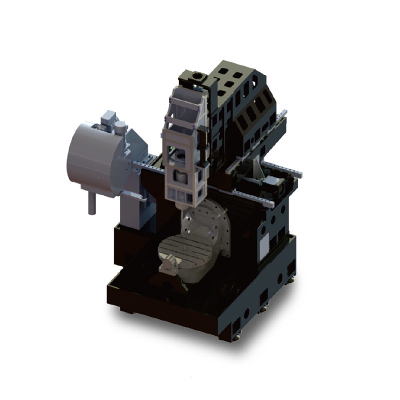
Five-axis machines add rotary joints, tilting components, and changing force directions. The buyer should review where the part sits relative to the rotary center, how fixture height affects leverage, and how stiffness changes at different orientations.
Ask the supplier to identify the longest tool, deepest feature, most extended axis position, and rotary angle used during the hardest cut. A short demonstration tool near the center of travel does not prove a deep-pocket operation at the edge of the envelope.
The complete chain includes machine structure, rotary bearings and drives, spindle, holder, tool, fixture, and part. Improving one element cannot fully correct weakness elsewhere.
Spindle Torque and Duty Matter More Than Top RPM Alone
Small finishing tools may use higher speed, while larger roughing cutters need useful torque at lower and medium rpm. Compare rated and peak power, torque curve, duty, spindle cooling, holder interface, and the planned cutting range for each critical operation.
A buyer evaluating this titanium setup should ask for estimated spindle load and material-removal strategy, not only maximum spindle speed. Include holders, tool overhang, balance, and runout in the review.
When long tools are unavoidable, consider whether reorientation can shorten effective reach. This is one of the strongest five-axis benefits: tilting the part may allow a shorter, stiffer tool and improve both access and cutting stability.
Rotary Envelope and Collision Control Need Real Tooling
Nominal workpiece diameter does not prove that the part can be machined. Model the raw stock, finished part, fixture, clamps, spindle nose, holder, longest tool, probe, enclosure, and chip guards at every planned orientation.
Confirm rotary limits, center height, table load, permissible unbalance, cable or hose clearance, and safe approach. Ask whether the CAM system and postprocessor accurately represent the delivered machine configuration.
Collision avoidance is a process, not a controller checkbox. It requires correct machine models, tool assemblies, fixture models, work offsets, simulation, prove-out, and disciplined program changes.
Coolant, Filtration, and Chip Evacuation Protect the Process
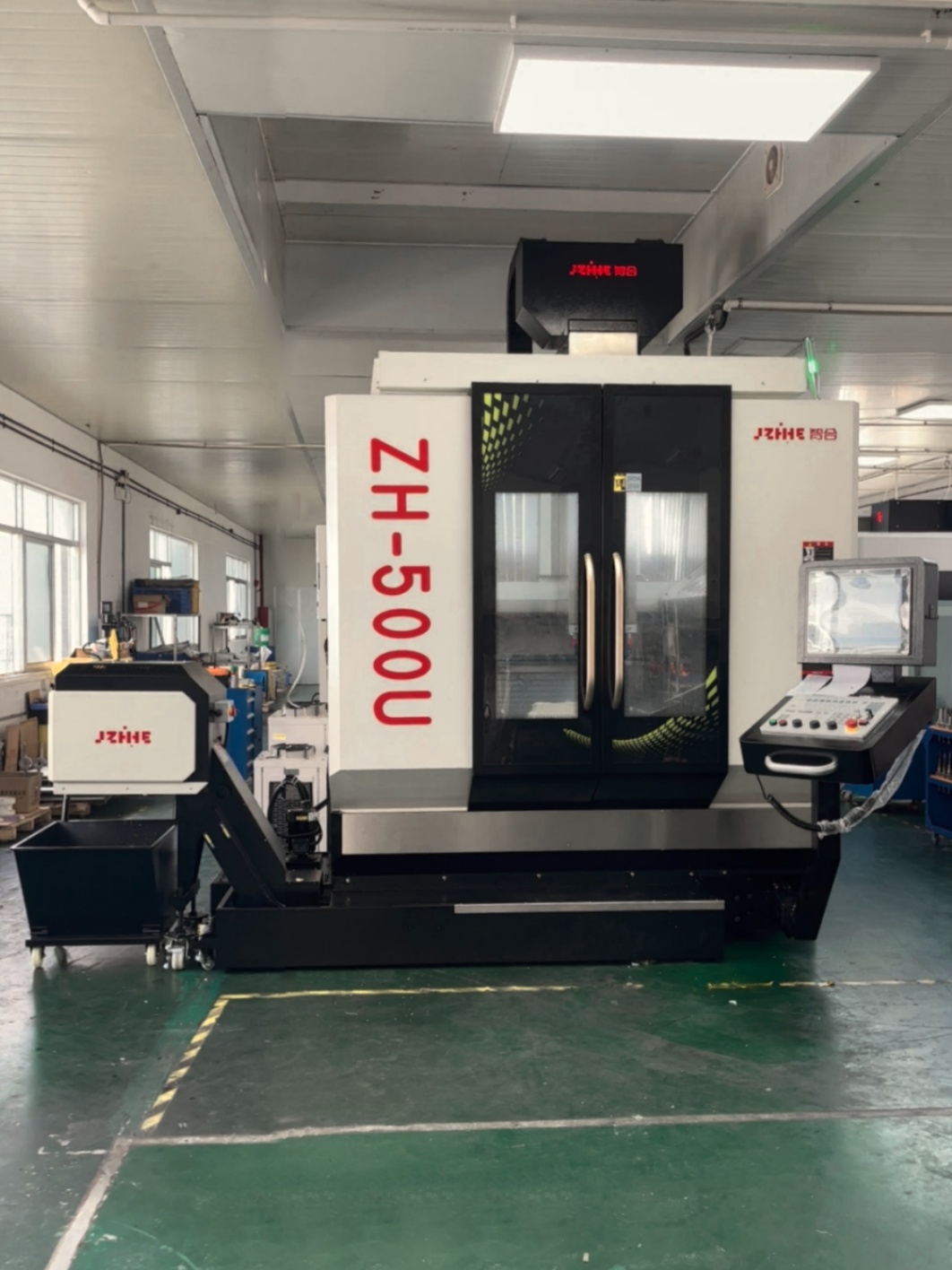
Review through-spindle coolant, pressure and flow, external nozzles, filtration, tank capacity, temperature management, washdown, conveyor type, and how chips leave deep cavities at tilted positions.
Coolant requirements depend on tool and operation. The quotation should state the offered system and why it fits the proposed route. Include maintenance access, filter replacement, and coolant monitoring in the operating plan.
During a trial, observe whether chips recut the surface, collect near the fixture, interfere with probing, or require manual clearing. Unplanned intervention can erase the cycle-time advantage of five-axis access.
Workholding Must Balance Support and Access
Titanium parts may be thin-walled, expensive, and highly finished. The fixture must resist roughing forces without distorting the part, while leaving enough access for multiple orientations.
Review locating strategy, clamping sequence, support under heavy cuts, release distortion, and how the part is transferred if a second operation remains. Consider probing for stock variation and in-process verification, but do not use probing as a substitute for a stable fixture.
The best fixture is not always the smallest. It is the fixture that supports the difficult cut, preserves the datum, clears the tools, drains chips and coolant, and can be loaded consistently.
Kinematic Calibration and Tool Center Point Control
Five-axis accuracy depends on linear axes, rotary-axis center and alignment, compensation, spindle condition, tool measurement, thermal state, and controller functions. A machine can pass linear-axis checks yet still show error when the tool center moves through several rotary orientations.
Ask how rotary kinematics are measured, calibrated, compensated, and rechecked. Confirm the machine warm-up, probe or calibration artifact, software method, report, and service procedure. Define who performs recalibration after installation or a collision.
For high-value parts, include a representative test that uses the rotary positions and feature relationships found in production.
CAM, Postprocessor, and Prove-Out Are Part of the Machine
The machine cannot create value if the programming chain is incomplete. Confirm supported CAM software, postprocessor responsibility, machine simulation model, tool-center-point functions, rotary limits, safe retract logic, and operator training.
Use the buyer's representative program during acceptance when possible. Record any manual edits required after posting. A process that depends on undocumented edits will be difficult to repeat across programmers and future revisions.
| Area | Evidence to request | Risk controlled |
|---|---|---|
| Cutting | Titanium grade, tools, load, wear, coolant, cycle | Unstable removal and short tool life |
| Envelope | Full stock, fixture, tool, rotary simulation | Collision or inaccessible features |
| Accuracy | Linear and rotary calibration plus trial part | Feature error across orientations |
| Programming | Machine model, post, simulation, prove-out | Manual edits and collision exposure |
| Production | Chip control, sister tools, probing, recovery | Repeated operator intervention |
Representative Trial Checklist
- Use the actual titanium grade and stock condition.
- Select the feature with the highest force, heat, reach, or accuracy risk.
- Record the machine, spindle, holder, tools, fixture, coolant, and program.
- Measure cycle time, spindle load, tool changes, manual stops, and chip clearing.
- Inspect critical features after unclamping.
- Document tool wear and finish at the end of the planned run.
- List required options, remaining limitations, and corrective actions.
Common Buying Mistakes
- Buying five-axis motion without a defined part family. Complexity should remove specific setups or access problems.
- Testing easy aluminum instead of titanium. The trial should expose the real thermal, force, chip, and tool-life conditions.
- Ignoring tool reach. Long tools can dominate stability even on a rigid machine.
- Using an incomplete machine model. Reliable simulation needs the delivered kinematics and fixtures.
- Skipping rotary calibration. Linear accuracy alone does not prove multi-axis feature relationships.
- Underestimating training. Programming, setup, simulation, probing, recovery, and maintenance all need ownership.
FAQ
Is simultaneous five-axis machining always required for titanium?
No. Many parts can use indexed 3+2 machining for most operations. Simultaneous motion should be used where contours, access, finish, or tool orientation require it.
What spindle is best for titanium?
There is no single answer. Match torque, power, duty, speed range, holder, cooling, and tool plan to the difficult operations on the representative part.
Can five-axis machining reduce tool overhang?
Often yes. Reorienting the part can let the spindle approach a feature with a shorter, stiffer tool, which may improve access, stability, and finish.
How should rotary accuracy be accepted?
Define the calibration method, conditions, report, pass limits, and a trial part that uses relevant rotary positions. Include installation-site verification when required.
What should be sent for a proposal?
Provide the drawing, titanium grade, stock size, finished weight, removal target, critical features, annual volume, cycle target, CAM system, factory constraints, and delivery destination.
Request a Titanium Process Review
To compare a 5 axis machining center for titanium, send Zhihe CNC the representative drawing, grade, stock, fixture concept, tool-reach risk, critical tolerances, annual volume, and CAM environment. Use the contact page to request a five-axis process proposal, trial-cut plan, machine recommendation, and quotation.