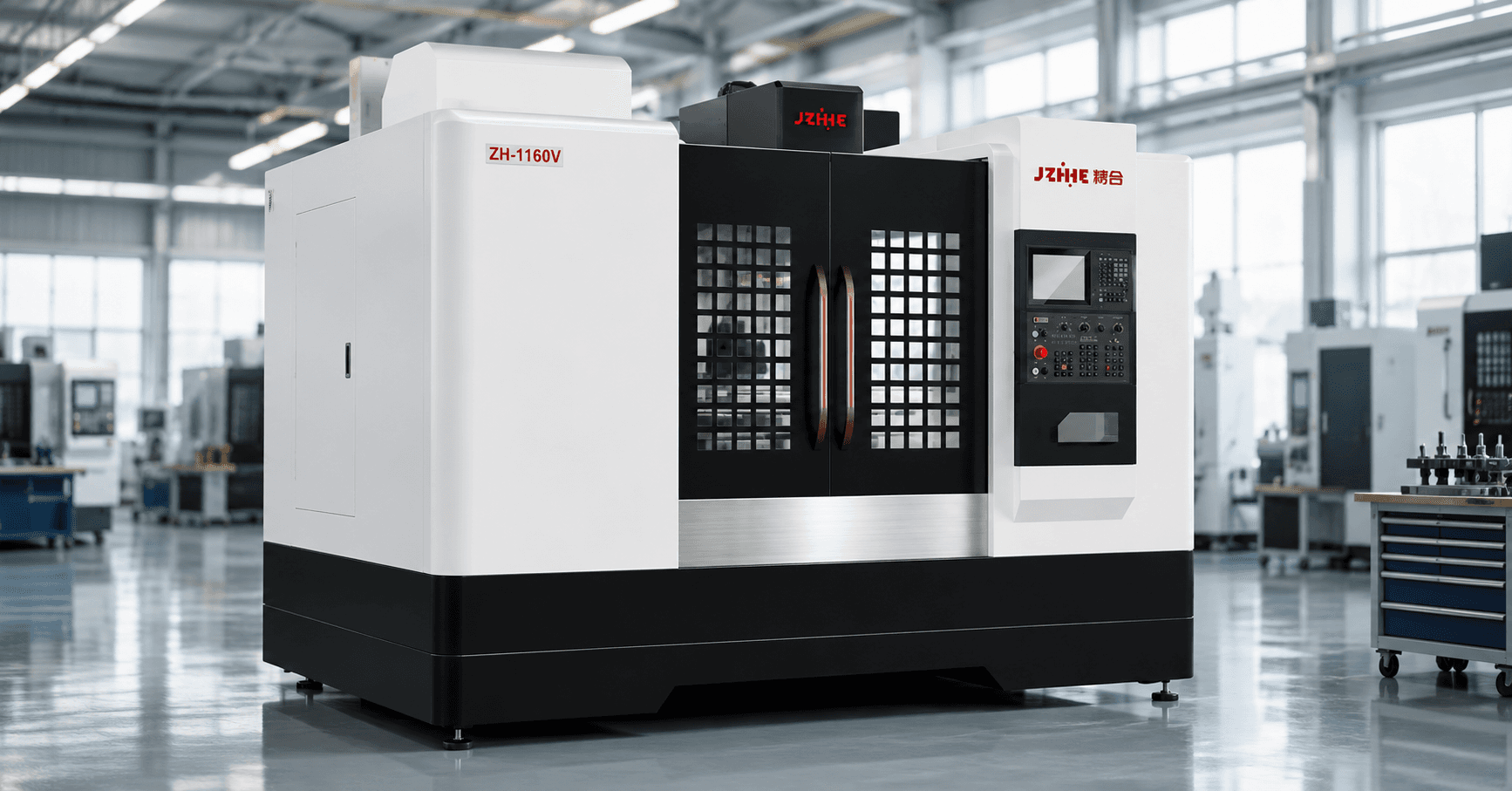
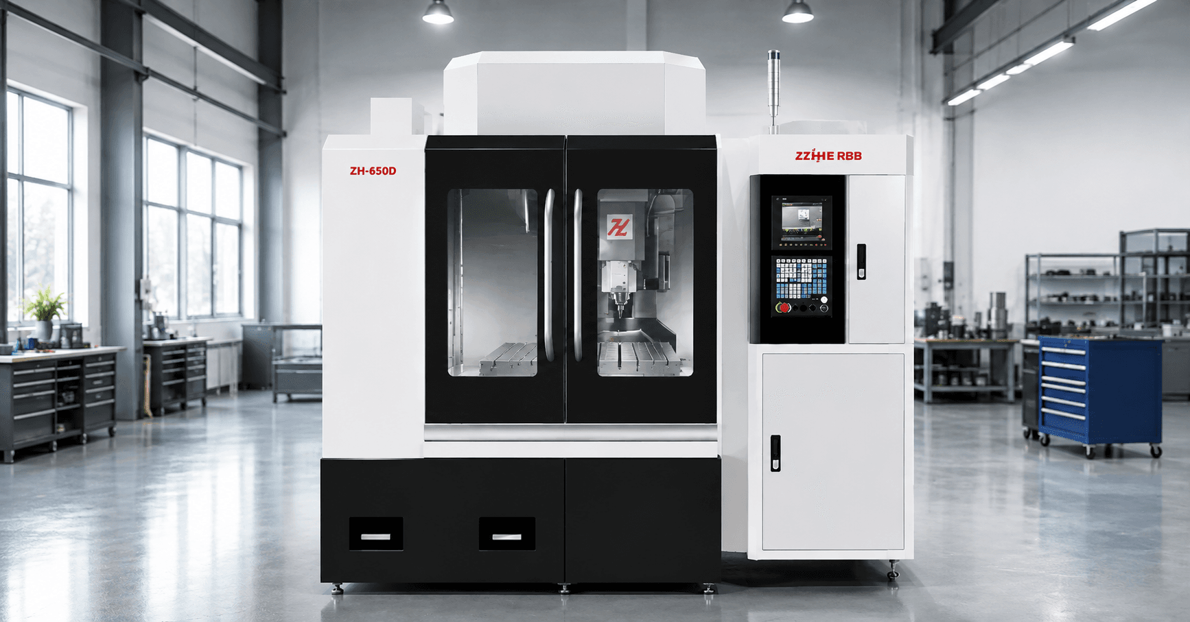
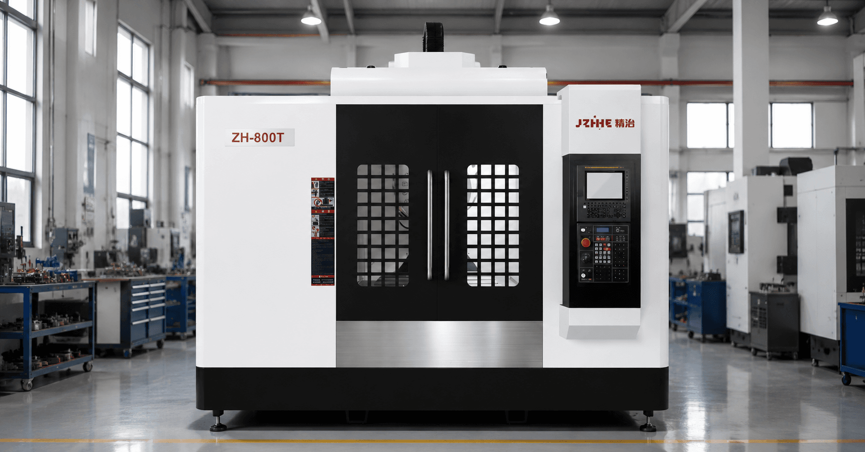
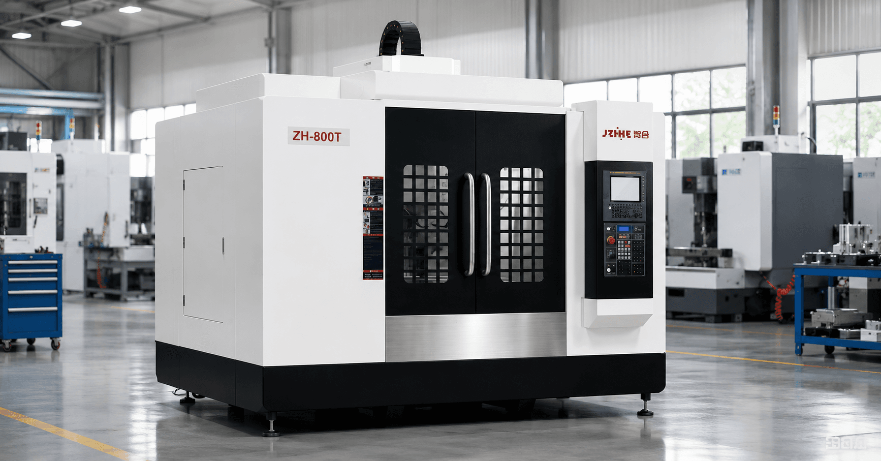
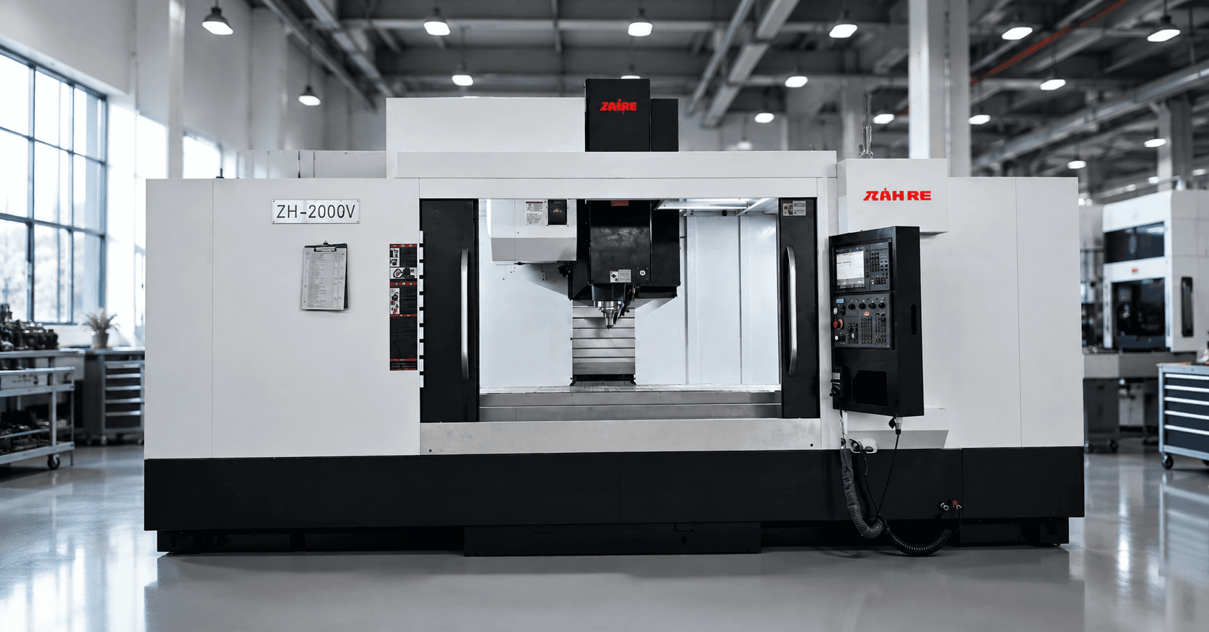
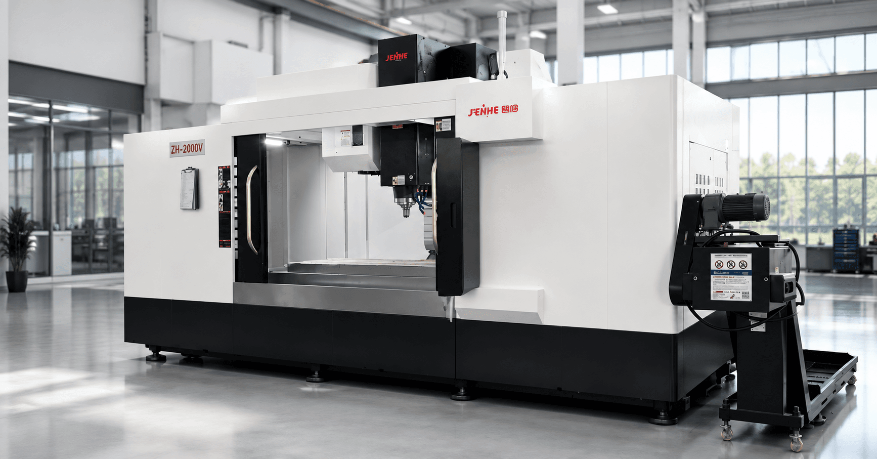
An aluminum profile machining center should be selected as part of a complete flow from incoming extrusion to inspected, protected, and packed component. Travel and spindle speed matter, but output is often controlled by profile variation, saw-cut accuracy, clamping zones, datum transfer, chip evacuation, changeovers, deburring, inspection, and handling damage.
This guide follows the production line in sequence. It helps buyers locate where accuracy and time are lost, decide which operations belong on the machining center, and build a trial that represents the real profile family rather than one convenient sample.
Stage 1: Define the Incoming Profile Condition
Record alloy and temper, extrusion cross-section, stock length, straightness, twist, wall variation, surface finish, protective film, saw allowance, and lot-to-lot variation. Thin sections can deform under clamping, while long stock can carry bow or twist into the setup. Decide which incoming conditions are supplier-controlled and which the machining process must absorb.
Use a profile-family drawing that shows the largest section, thinnest wall, longest length, tightest feature, most difficult end condition, and most sensitive cosmetic surface. These extremes define the process window better than an average part.
Stage 2: Build a Clamp-Zone Plan
Mark functional datums, machining features, forbidden clamp areas, weak walls, cosmetic faces, sawed ends, and support points. Define clamp sequence and force. A fixture that forces a bowed profile flat can produce a correct in-machine measurement but a distorted free-state part after release.
| Zone | Control question | Typical response |
|---|---|---|
| Primary datum | Which surface establishes the assembly reference? | Continuous support or controlled locating pads |
| Weak wall | How much clamp pressure can it accept? | Distributed support and limited force |
| Machining area | Will clamps block tools or chips? | Repositioned clamps or staged operations |
| Cosmetic face | How is marking prevented? | Protected contact and clean handling |
| Long span | Can the profile vibrate or sag? | Intermediate supports and short tools |
Stage 3: Assign Operations to Process Zones
Group features by top, side, end, and angled access. Record holes, tapping, slots, pockets, cutouts, counterbores, end milling, and datum features. Decide whether the machine completes the part in one setup, whether it uses indexed or multi-head access, or whether sawing and end work remain separate.
An aluminum profile machining center creates the most value when it reduces manual transfers without creating an overly complex fixture. Compare one long integrated cycle with two balanced operations. A second operation may be faster and easier to maintain if it isolates end work, deburring, or inspection.
Stage 4: Design Chip Flow Around the Profile
Aluminum chips can collect inside hollow sections, behind clamps, in slots, and under locating surfaces. Define coolant or minimum-quantity lubrication strategy, air use, enclosure extraction, fixture drainage, chip conveyor, cleaning access, and final internal-passage inspection. Avoid relying on manual air blow without considering safety and contamination.
Stage 5: Plan Changeovers by Profile Family
List common cross-sections, datum locations, lengths, tool sets, programs, clamps, inspection gauges, and packaging. Use modular fixture bases and replaceable nests where they reduce reset risk. Give every revision a controlled identifier so programs, fixtures, setup sheets, and drawings remain aligned.
Measure changeover from last accepted part to first accepted part, not from program stop to cycle start. Include material retrieval, fixture cleaning, tool verification, offset confirmation, first-off inspection, and documentation.
Stage 6: Balance the Whole Line
Calculate capacity using saw time, loading, clamping, machining, unloading, deburring, washing, inspection, marking, protection, packaging, maintenance, and expected losses. The machining center may not be the constraint. A fast machine can wait for profile preparation or create a queue at manual deburring.
- Measure accepted parts per shift by profile family.
- Separate automatic time from attended operator time.
- Model peak product mix, not only annual average volume.
- Define buffers without allowing profiles to be scratched or mixed.
- Identify the next constraint before purchasing additional spindle capacity.
Stage 7: Accept the Process With Extreme Samples
Trial the longest profile, weakest section, most complex feature pattern, and fastest repeat part. Use production clamping, tools, lubrication, handling, deburring, and inspection. Measure free-state straightness, datum relationships, hole positions, slots, end geometry, burrs, cosmetic condition, cycle, and changeover.
Where a Different Machine May Be Better
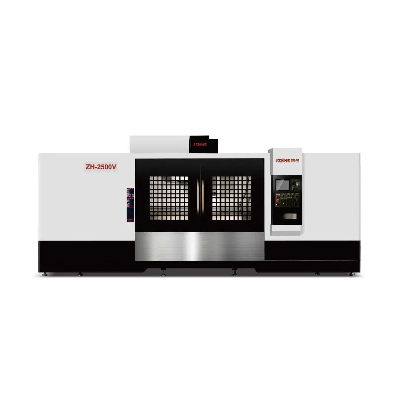
A standard vertical center may be more economical for short rigid profiles and mixed small batches. A dedicated transfer or multi-head line may be better for one high-volume stable part. A gantry or longer-travel platform may be required for envelope and support. State these boundaries before requesting a quote.
FAQ
Should long aluminum profiles be forced flat during machining?
Only if the drawing and assembly condition justify it. Otherwise the part may spring back after release. Define free-state requirements and clamp force.
What usually limits output?
Loading, clamping, cleaning, deburring, inspection, changeovers, and handling can be more limiting than cutting time.
How should cosmetic surfaces be protected?
Control contact materials, fixture cleanliness, chip paths, operator handling, intermediate storage, film, and packaging throughout the line.
Which drawings should be sent for selection?
Send the profile cross-section, longest part, shortest part, tightest tolerance, feature extremes, cosmetic requirements, volumes, and current process flow.
Request a Profile-Family Line Review
To select an aluminum profile machining center, send Zhihe CNC the extrusion drawings, length range, alloy, straightness, clamp limits, feature map, volumes, changeover targets, inspection method, and packaging needs. Review the vertical profile machining platform, compare the broader vertical machining center range, and use the contact page for a line and trial recommendation.