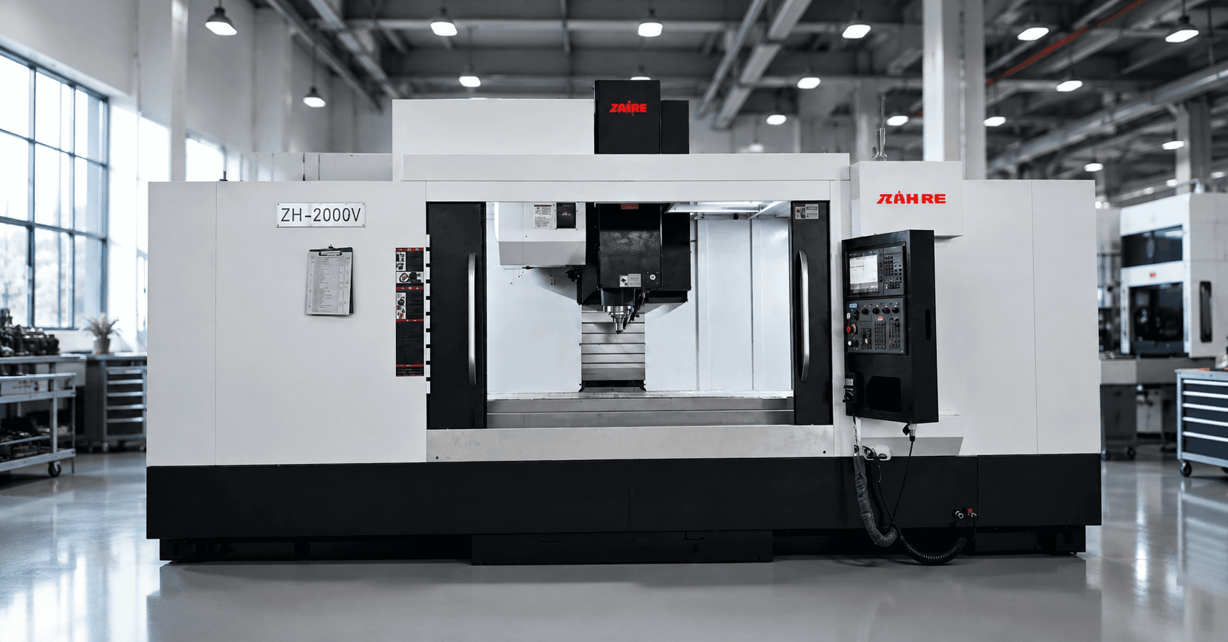
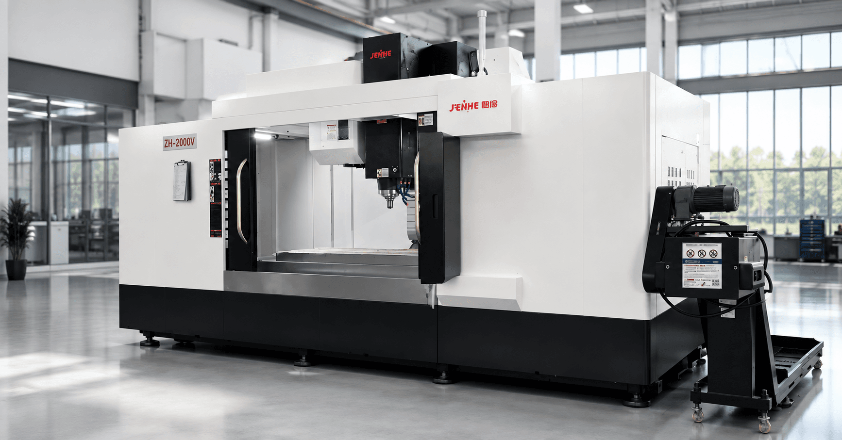
A CNC machine for communication equipment parts should be selected around the interfaces that make the finished enclosure, heat sink, chassis, radio housing, or connector plate function in assembly. Travel and spindle speed matter, but the process usually succeeds or fails at six linked controls: datums, heat-transfer faces, connector locations, thin-wall stability, cosmetic protection, and cleanliness.
This interface-chain method keeps machining decisions connected to product performance. It also prevents a local dimension from passing while the complete assembly suffers from poor sealing, connector mismatch, thermal contact, distortion, trapped chips, or visible handling damage.
Link 1: Establish the Enclosure Datum System
Identify the surfaces that locate the part in the final assembly. Separate functional datums from convenient machining references. Mark gasket faces, board mounts, connector planes, antenna features, rail contacts, cover joints, and grounding points. Record which relationships span several faces and which can be inspected before the part is unclamped.
Build the process from the most stable blank surfaces and preserve the assembly datum through later setups. If a second setup is required, define how the datum is recovered and verified. Do not assume cast, extruded, or saw-cut stock has enough consistency to act as an uncontrolled reference.
Link 2: Protect Heat-Transfer Faces
Map heat-sink bases, thermal-pad seats, cold-plate contacts, fin roots, and surfaces that mate to electronic assemblies. Define flatness, roughness, waviness, cleanliness, coating allowance, and inspection condition. A surface can meet a local finish value yet perform poorly if it bows after unclamping or contains handling marks.
Plan stock removal to balance stress. Use support and clamp force that do not temporarily flatten a flexible housing. Measure critical faces in the free state when assembly performance depends on the released shape. Record the temperature and time between machining and inspection where thermal response matters.
Link 3: Hold Connector and Hole-Pattern Relationships
Connector cutouts, threaded inserts, board mounts, alignment pins, and cable entries often form one functional pattern. Create a feature map showing datum references, access direction, tool reach, burr direction, edge distance, and inspection method. Group critical features into the minimum number of controlled orientations.
| Interface | Machining risk | Required evidence |
|---|---|---|
| Connector opening | Position, corner radius, burr, cosmetic edge | Profile and assembly check |
| Board mounting pattern | Accumulated true-position error | Datum-based hole report |
| Gasket face | Flatness, finish, scratches, chip marks | Surface and sealing review |
| Threaded feature | Tap life, depth, insert fit, chip retention | Gauge and cleanliness record |
| Ground contact | Coating mask, surface condition, location | Drawing and assembly verification |
Link 4: Release Thin Walls Without Distortion
Thin ribs, fins, pockets, and large windows can move as material is removed. Define roughing, rest periods where needed, semi-finishing, finishing allowance, tool engagement, support, and clamp sequence. Monitor wall movement after each major stage rather than discovering distortion only at final inspection.
Use short, rigid tools where access permits. Control tool wear because a dull cutter increases force, heat, burrs, and wall deflection. A CNC machine for communication equipment parts must support the process window, but fixture design and stock-removal sequence remain equally important.
Link 5: Separate Functional and Cosmetic Control
Mark protected faces on drawings and setup sheets. Define contact materials, part trays, chip-free supports, glove requirements, washing, deburring, coating preparation, and packaging. Cosmetic defects often occur after the machining cycle during unloading, stacking, manual edge work, inspection, or transport.
Use a defect standard with acceptable and unacceptable examples. Track where marks occur and change the handling step rather than polishing every part. Keep cosmetic repair from changing a functional edge, sealing face, thickness, or coating preparation.
Link 6: Close the Cleanliness Loop
Identify blind holes, intersecting passages, fins, threaded features, and internal pockets that trap chips or coolant. Define in-machine evacuation, fixture drainage, washing, air use, drying, inspection, and packaging. Cleanliness acceptance should state the method, not just the word clean.
Use assembly feedback. Record connector fit, gasket compression, board alignment, thermal contact, grounding, fastener engagement, and field or test failures. Feed these results back to machining controls so the process is optimized for the complete product.
Run an Interface-Chain Trial
- Freeze the drawing, blank, fixture, tool list, program, and inspection method.
- Identify the highest-risk datum, thermal, connector, wall, cosmetic, and cleanliness interfaces.
- Run a production-like sequence with normal tool life and handling.
- Measure the part after unclamping and cleaning where required.
- Complete a representative assembly check instead of relying only on isolated dimensions.
- Record the proven window, interventions, defects, and remaining limits.
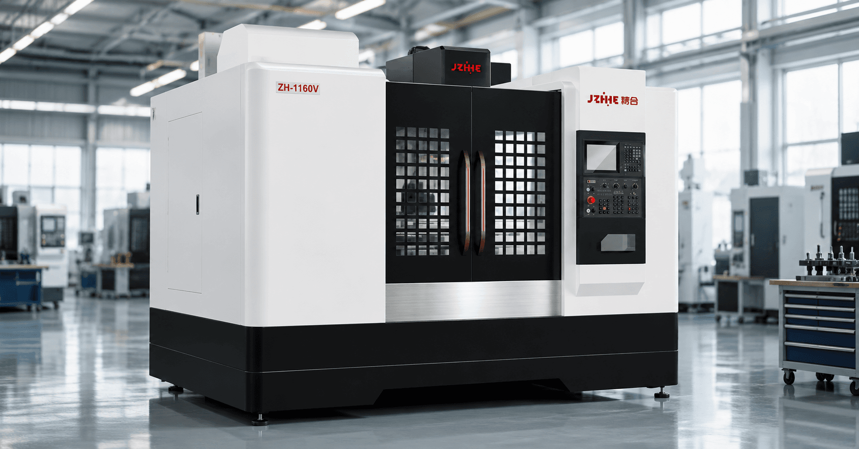
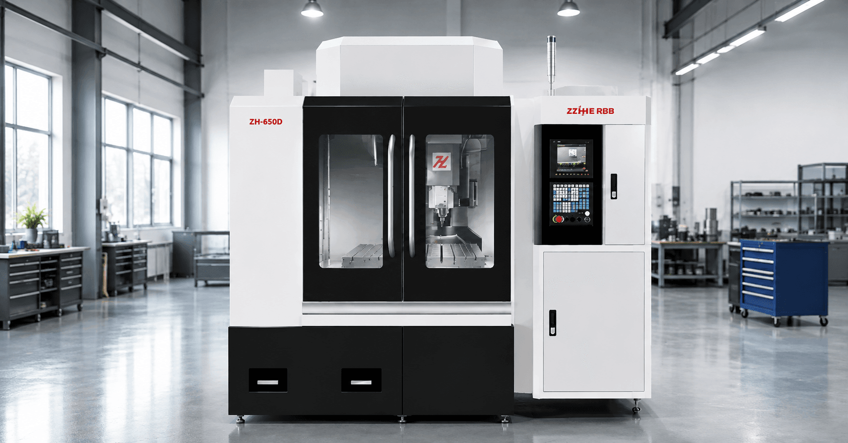
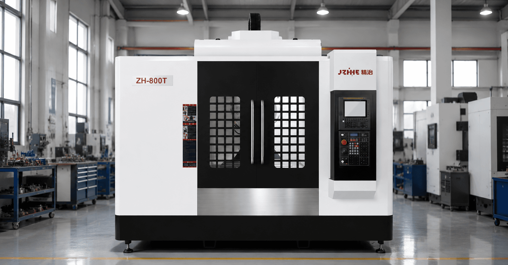
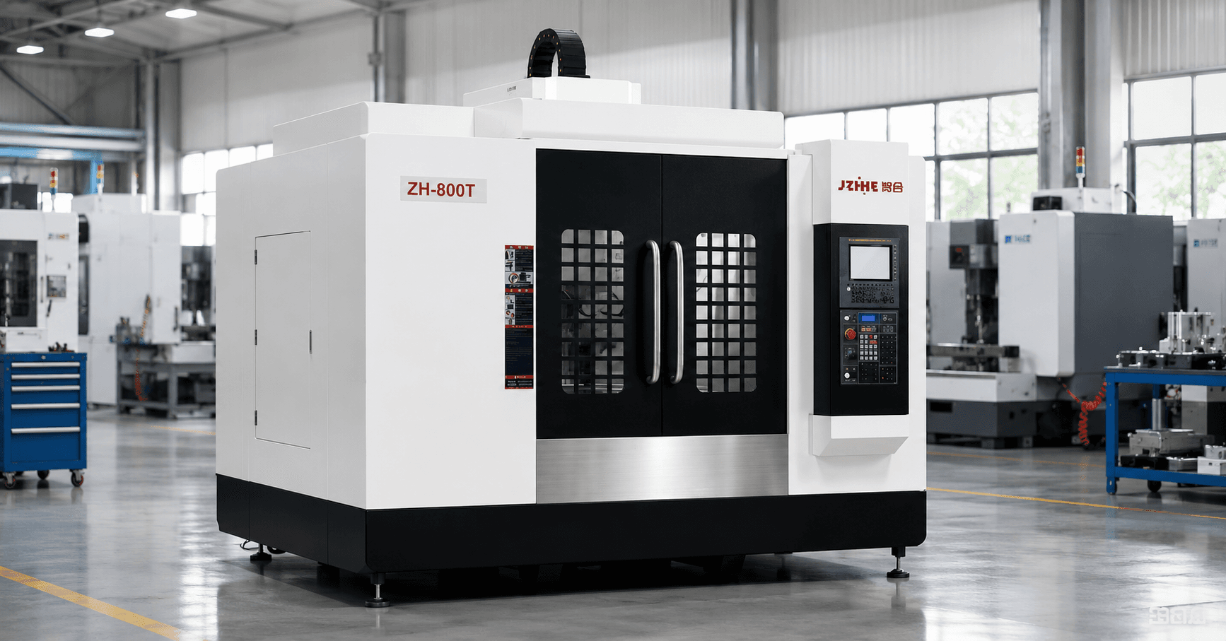
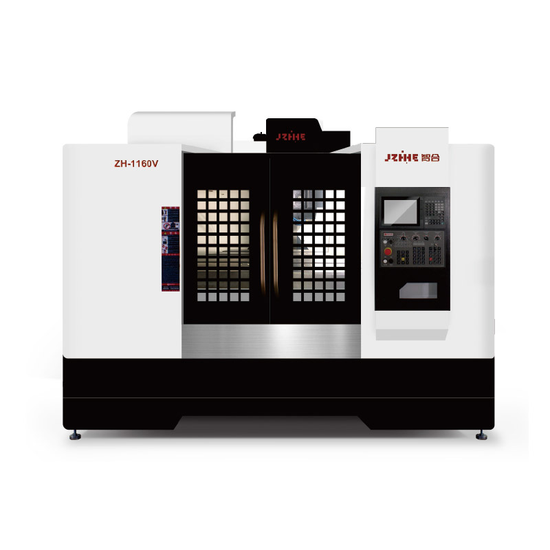
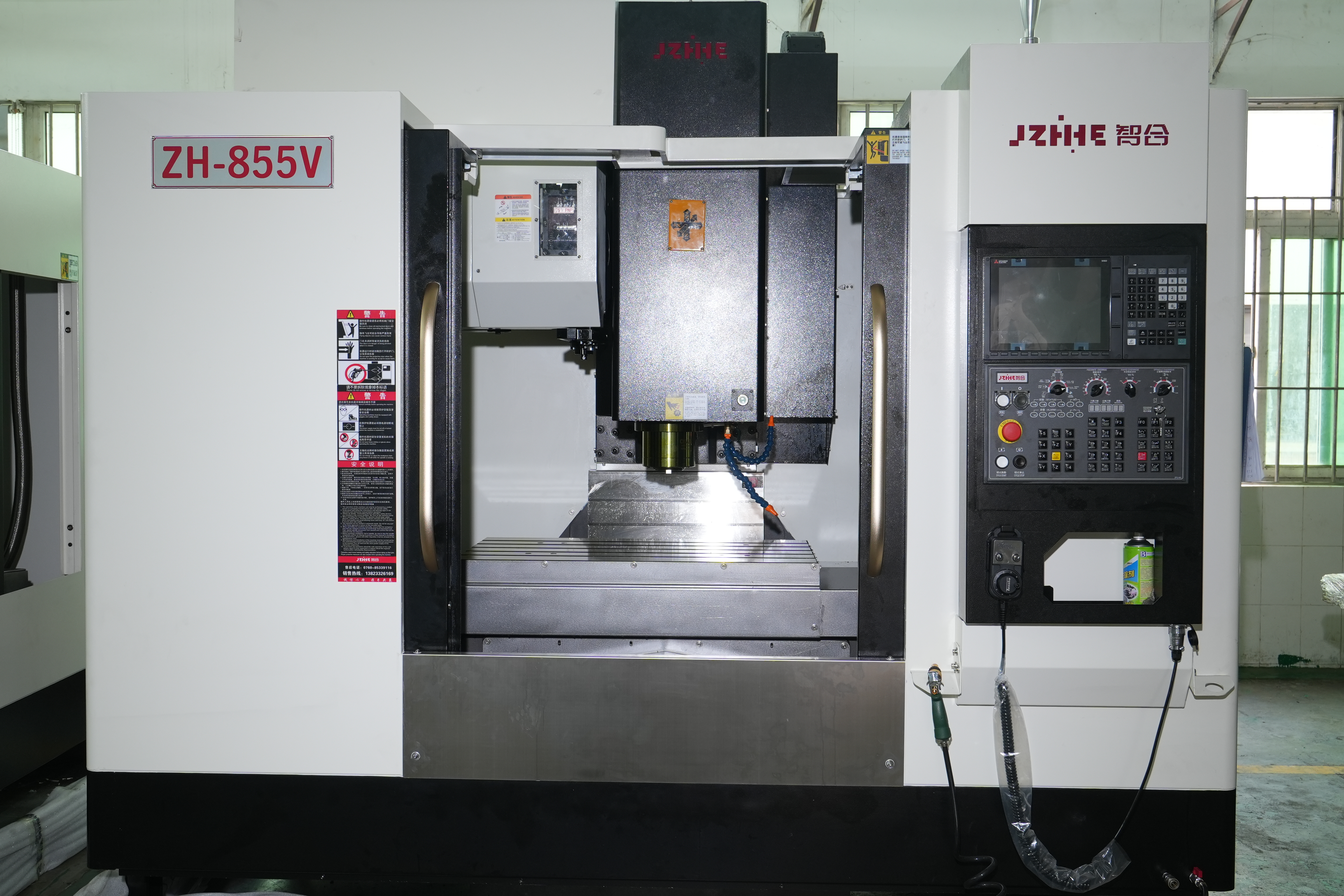
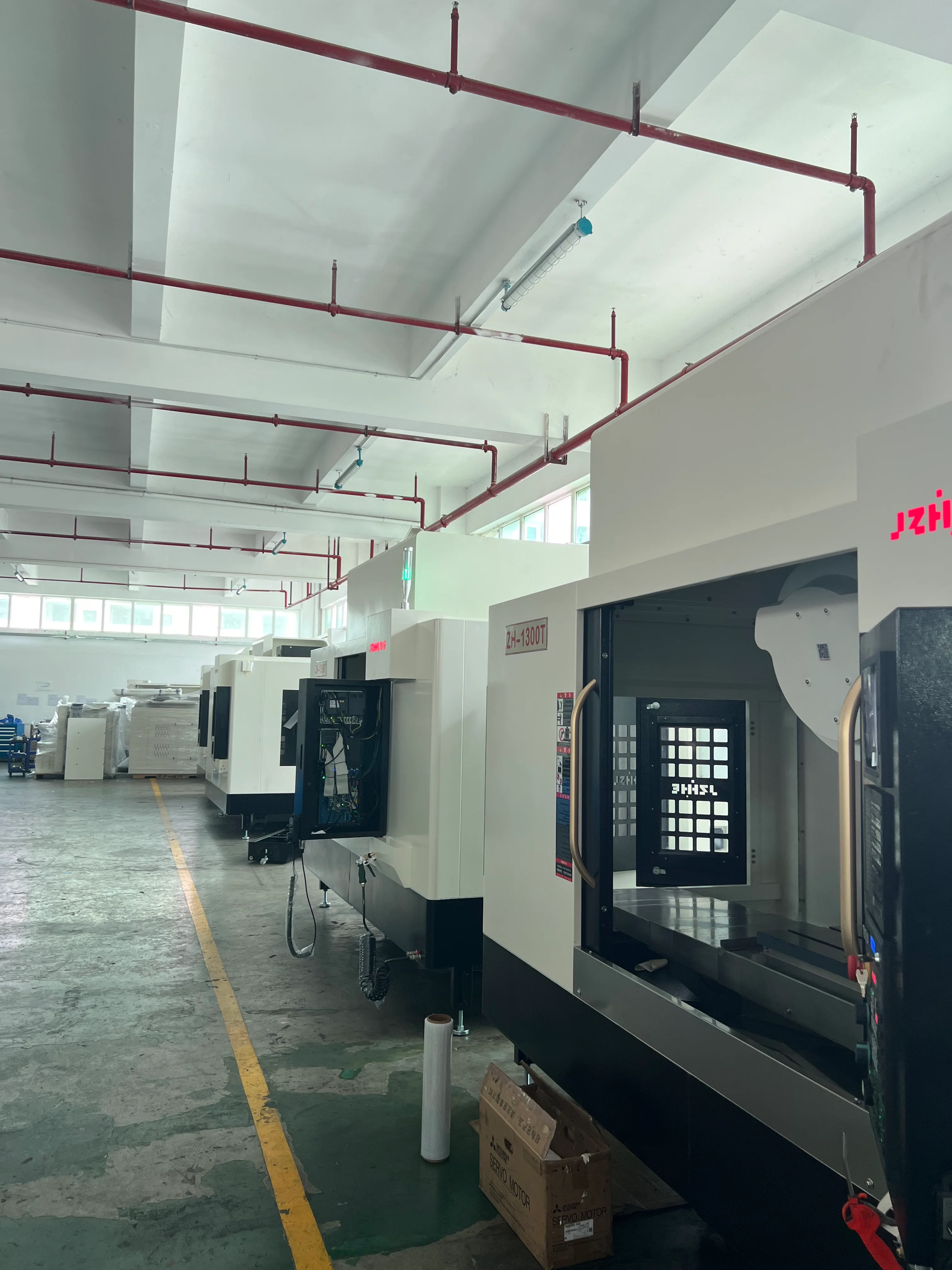
Review the vertical machining center range as one possible architecture, then compare it with other Zhihe platforms according to access, volume, and setup consolidation.
Where This Method Has Limits
Not every communication component requires a dedicated machine architecture. Simple plates or low-volume housings may run effectively on standard equipment with controlled fixtures and handling. Product-specific electromagnetic, thermal, coating, sealing, and cleanliness requirements must come from the buyer's engineering and quality system; a machining trial alone does not certify the complete electronic product.
FAQ
Which datum should be machined first on an enclosure?
Start from the stable reference that best preserves critical assembly relationships, while accounting for blank variation and later setup recovery.
Why measure a housing after unclamping?
Clamping can temporarily flatten or distort thin walls. Free-state measurement shows the shape presented to the final assembly.
Should cosmetic surfaces be inspected only at the machine?
No. Inspect after deburring, washing, coating preparation, handling, and packaging because many visible defects occur downstream.
What should be included in the trial assembly?
Include the interfaces most sensitive to position, flatness, sealing, thermal contact, grounding, fastener fit, or cleanliness.
Submit an Interface Map
To evaluate a CNC machine for communication equipment parts, send the controlled drawing, blank process, material, protected surfaces, critical datums, heat-transfer faces, connector patterns, wall thicknesses, cleanliness requirement, batch size, annual volume, and assembly checks. Use the contact page to request a process review, and consult Zhihe CNC's manufacturing background when defining supplier responsibilities.