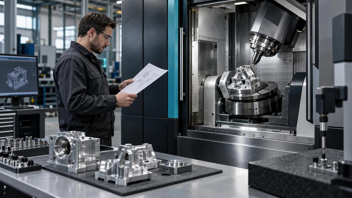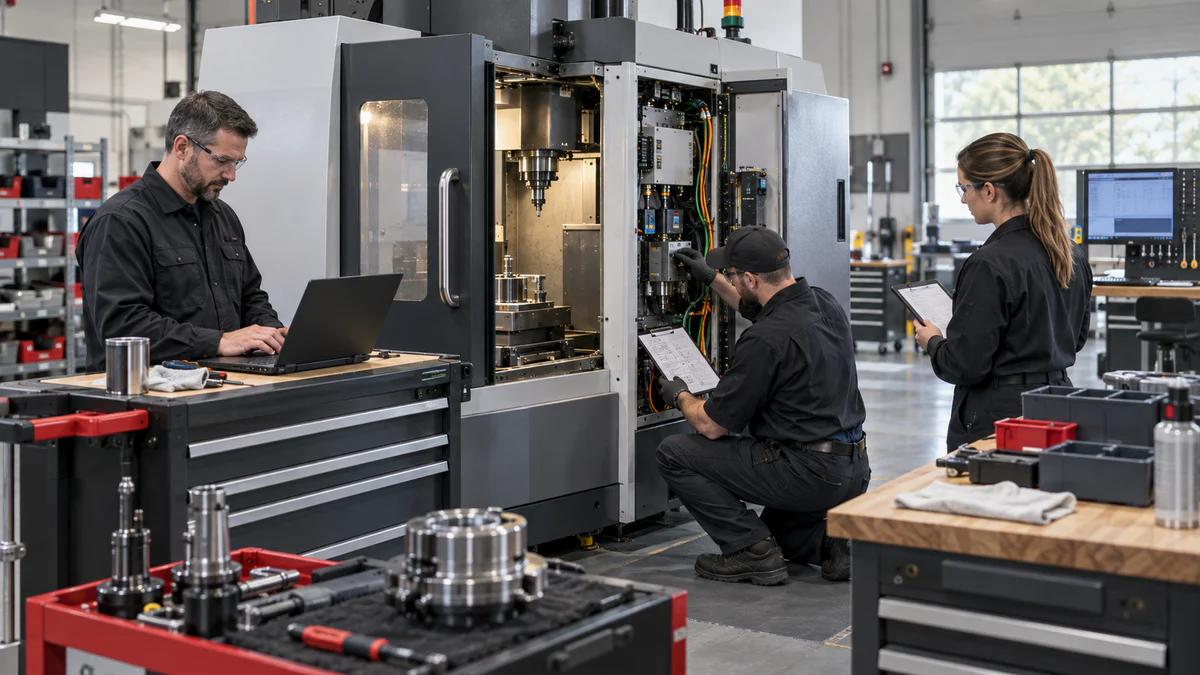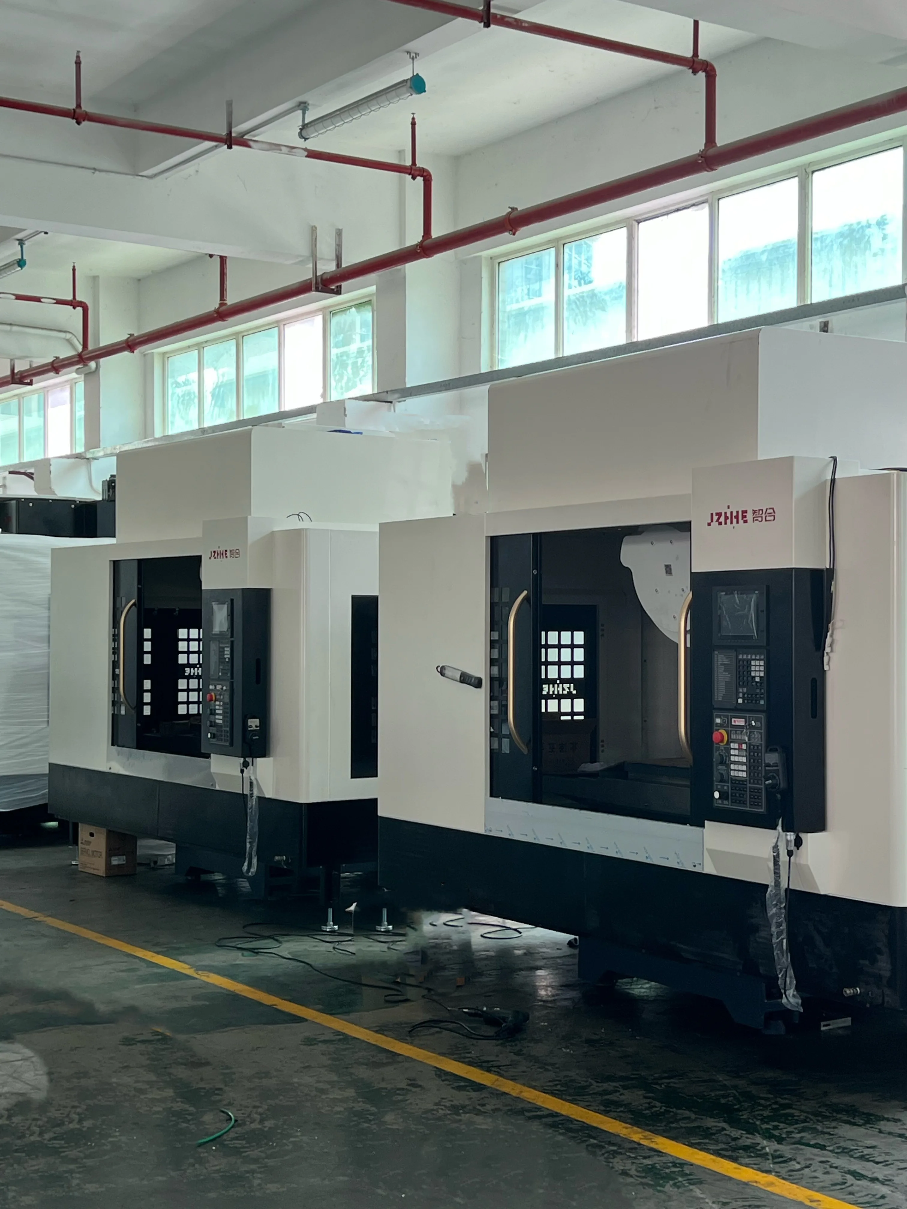
CNC machine fixture selection should begin with the workpiece datums, cutting-force path, distortion risk, tool access and required output, not with a familiar vise or an impressive fixture catalogue. A buyer can make the decision repeatable by grouping representative parts into families, recording what must stay controlled, and trialling the fixture and machine as one process.
This article is for manufacturing engineers, estimators, production supervisors and machine buyers. It compares fixture routes without pretending that one workholding method suits every material or tolerance. Final designs, clamp forces, guarding and operating procedures need competent engineering and validation for the actual part.
Build a Part-Family Card Before Comparing Hardware
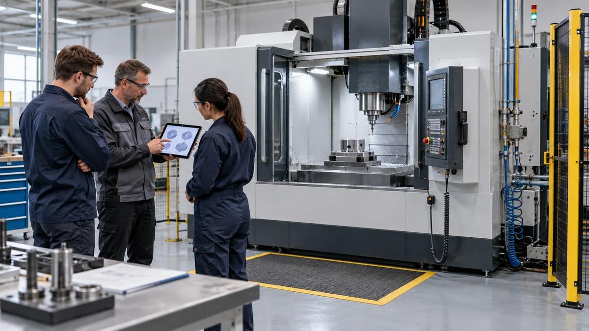
Choose a demanding but representative part from each family. On one page, show the incoming stock, material condition, important datums, critical features, tolerance relationships, surface requirements, burr-sensitive edges, thin walls, batch size and expected variants. Mark the faces that need cutter, probe and gauge access.
Add what happens before and after machining. A casting may arrive with variable draft or scale. A sawn blank may vary in length. A finished face may become the datum for a later operation. Washing, deburring, heat treatment or coating can change how a part may be held or inspected. These facts often matter more than the fixture's brand.
For CNC machine fixture selection, the card prevents one successful sample from being treated as proof for an entire product range. Put drawing revisions and material conditions on the card, then separate confirmed facts from assumptions that still need a trial.
Draw the Datum Story From Blank to Released Part
Trace how the first setup creates or inherits datums, how later setups locate from them, and where inspection closes the loop. If a critical bore and mounting face are made in different setups, show the relationship that must survive reclamping. If a thin wall is released after roughing, identify when distortion can appear and which state the drawing dimension describes.
A common locating concept uses a primary, secondary and tertiary constraint sequence, but the actual contact geometry belongs to the fixture designer. More contact is not automatically better. Extra supports can help a compliant part, or they can over-constrain an inconsistent casting and move the part when clamps close.
Make datum transfer visible on the process sheet. The operator should know which surfaces must be clean, which contacts are fixed, which supports are adjustable and which feature confirms correct seating. That is more useful than a setup photograph without a location scheme.
Put Loads Through the Supports, Not Through Hope
Sketch the likely cutting-force direction for roughing, drilling, tapping and finishing. Show where those loads enter the workpiece and how they reach fixed supports. Then add clamp directions. A clamp that pushes the part away from its locators creates a different process from a clamp that seats it predictably.
Thin, long or open-section parts deserve a distortion review. Clamping can bend the blank before machining; material removal can release residual stress; unclamping can reveal a dimension that looked acceptable in the fixture. Define where inspection occurs, when the part is released, and whether an intermediate rest period or recheck is part of the process.
The NIST paper on a flexible fixturing system describes modelling contact, fixture forces, deformation and stress. It is useful evidence that workholding is a load-path problem. It is not a ready-made fixture design or a substitute for trial data on the buyer's workpiece.
Use a Route Matrix Instead of a Single Favorite
Score plausible routes against the family card. Keep the scale simple and require a note for every high or low rating. CNC machine fixture selection becomes easier to audit when the reasons sit beside the score.
| Route | Usually worth considering when | Questions that decide the fit |
|---|---|---|
| Standard vise or chuck | Geometry is regular, access is adequate and changeovers matter | Can the part seat repeatably without crushing or blocking tools? |
| Modular plate and locators | Families share hole or datum patterns but still change often | Are modules rigid, mistake-proofed and cleanable in the actual chip flow? |
| Dedicated fixture | Volume and stability justify purpose-built hardware | How will wear, revisions, spare components and end-of-life changes be managed? |
| Pallet or tombstone arrangement | Multiple faces or queued production benefit from off-machine loading | Does the full loaded envelope clear tools, probes, doors and pallet motion? |
| Multi-part fixture | Small parts and repeated cycles can share one setup | Is clamping even, is a missing part detected, and can every station evacuate chips? |
| Vacuum or other application-specific holding | Broad surfaces or delicate parts make conventional clamps difficult | What failure mode, backup retention, leakage limit and material condition apply? |
Do not total the scores before deciding the weights. Prototype responsiveness, unattended stability, changeover time and surface protection may carry different importance in different factories. A decision matrix is a structured argument, not a machine that chooses for the engineer.
Decide Whether Flexibility or Repeatability Pays
A flexible fixture can shorten the path to a new drawing and reduce dedicated inventory. It may demand more setup discipline, more probing or a larger clearance envelope. A dedicated fixture can shorten loading and reduce operator choices once stable, but engineering changes and low utilization can make it expensive to own.
Compare the complete production route: fixture design, manufacture, prove-out, setup, loading, cleaning, probing, cutting, inspection, maintenance, storage and change control. The cheapest fixture on a purchase order may consume the most spindle time. The most elaborate fixture may never recover its engineering cost if the part family changes every month.
Use at least three production states in the estimate: first article, normal repeat batch and recovery after a held part or worn component. This keeps an elegant best-case cycle from hiding the work needed to keep the process running.
Check Tool, Probe and Chip Access in the Same Model
Place the longest tool assembly, spindle nose, probe, coolant nozzles and any head or rotary-axis geometry around the loaded fixture. Review approach and retract moves, not only the cutting position. A clamp can clear the finished surface yet block the toolholder on entry. A tall tower can open more faces while reducing reach or usable tool length.
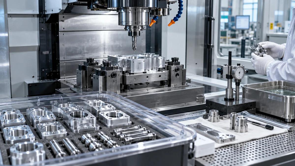
Plan where chips go during each operation. Pockets around locators can prevent full seating. A compressed-air habit may move chips from one contact to another or create a safety and mist issue. Prefer contacts that can be inspected and cleaned with a defined method. Where flushing or air is used, include it in the actual cycle and risk assessment.
Inspection access belongs in the same review. If the process depends on probing, identify stylus reach, calibration, protected moves and what the result changes. If a feature must be gauged off-machine, define the released state and the datum transfer rather than assuming the fixture result will match the inspection result.
Match the Fixture Route to the Machine Architecture
The machine and fixture define one envelope. A vertical machining center can provide straightforward top access and familiar loading for many plate, mold and prismatic jobs. A horizontal machining center can support multi-face work and pallet flow where the part and volume justify it. A five-axis machining center may reduce reclamping for complex orientation, but the fixture must preserve rotary clearance and tool reach.
For CNC machine fixture selection, compare usable travel after the workholding is installed, not nominal travel alone. Include the largest blank, locators, clamps, risers, pallet, probe and longest required tool. Check table load and distribution using current supplier data for the proposed configuration. Never infer permissible load or clamping practice from a generic machine-family label.
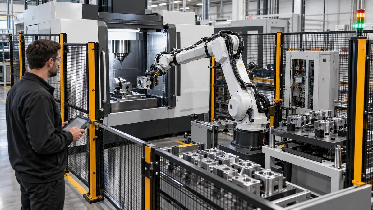
Also compare the human interface. Can the operator load the part without reaching around sharp stock? Are connectors keyed and protected? Can a heavy fixture be changed using the site's handling equipment? Does the door opening support the planned automation? The productive envelope includes hands, carts and maintenance access as well as axis motion.
Protect Safety Functions and Access Boundaries
Workholding does not replace machine guarding, and a custom fixture must not defeat interlocks or create a new ejection path. Review broken-tool, loose-part, hydraulic or pneumatic loss, missing-part and incorrect-loading conditions. Decide how the machine is isolated before cleaning, adjustment or fixture change.
OSHA's machine-guarding introduction separates the point of operation, power-transmission equipment and controls, while noting that safeguarding needs vary by machine and operator involvement. Apply the destination market's laws and risk-assessment process; this article does not certify a fixture or prescribe a safeguarding solution.
Document any stored energy in clamps, accumulators, springs or heavy moving elements. Identify a safe state for loss of power and a method for releasing a part without improvisation. Review sharp edges, pinch points and manual handling during the states when doors are open and production pressure is high.
Run a Red-Tag Fixture Trial
Before the trial, attach a red tag to every unproven assumption: stock variation, locator contact, clamp setting, tool clearance, chip clearing, probe logic, cycle time, inspection method and operator step. The purpose is not to make the fixture look finished. It is to remove tags with evidence or convert them into controlled limitations.
Run the complete sequence with representative material and tooling. Include cleaning, loading, seating confirmation, cutting, probing, unloading and inspection. Repeat enough cycles to expose variation relevant to the agreed decision; one demonstration part cannot establish long-term capability. Record tool state, offsets, environmental conditions and any manual intervention.
CNC machine fixture selection is complete only when the accepted route has owners for setup, inspection, maintenance and change. Keep failed or held pieces when they explain a problem. A clean final sample without the path that produced it is weak evidence.
Read the Pattern Across Parts, Not Just One Result
Plot measurements in machining order and by fixture station. This pattern check gives CNC machine fixture selection evidence beyond the first acceptable sample. A steady shift can suggest tool or thermal change. One station that differs can point toward a contact, clamp or local chip problem. A jump after reload can reopen the seating method. These are investigation clues, not automatic diagnoses.
Compare the part in its clamped and released states where distortion is relevant. Mark where the part was measured and which datum construction was used. If a correction improves one feature while another degrades, review the datum and force path before adding more offsets.
Close each red tag with one of four outcomes: proven in the stated range, controlled by a documented step, accepted as a limitation, or rejected with a new route required. That short vocabulary keeps trial notes from dissolving into comments such as "looks okay."
A Short Example: Four Castings, One Misleading Vise
Imagine four pump-body castings that share outside dimensions but differ in port direction and an internal machined face. A standard vise holds the first sample and gives good access from above. On the second variant, however, the casting draft changes the contact, one clamp crosses a probe path, and chips collect beneath a low boss.
A part-family review separates two locating schemes instead of forcing all four parts into one setup. The team adds a controlled support for the weaker casting, moves the seating check into the operator sequence and tests a modular base that preserves common mounting while allowing variant-specific locators. The example is illustrative, not a customer result or a promise that a modular fixture is always best.
The lesson is that similarity should be proven at the datum and load-path level. Outside dimensions alone can hide the feature that makes a shared fixture unstable.
Questions That Change the Fixture Decision
Is a three-jaw chuck or vise accurate enough?
Accuracy cannot be decided from the device name. The answer still depends on the part contacts, stock variation, jaw or insert condition, clamping behavior, datum transfer, cutting loads and inspection results in the actual process.
When does a dedicated fixture make commercial sense?
It becomes a candidate when repeat volume, loading time, stability or mistake-proofing can repay the design, manufacture, maintenance and change cost. Compare it with a flexible route over the expected product life.
Should more clamps be added to stop movement?
Not automatically. More force or more contacts can distort a part or over-constrain variable stock. Review the load path and support condition, then validate the setting with representative pieces.
Can probing correct a poor fixture?
Probing can identify position or support a controlled offset strategy, but it does not remove loose seating, distortion, blocked access, contamination or an unsafe clamp condition. Define what the probe result is allowed to change.
How should fixture repeatability be checked?
Use an agreed loading, cleaning, clamping and measurement procedure over repeated setups. Record the fixture station, operator-relevant steps, gauge method and part state so the result can be traced.
What should be sent for a CNC machine fixture selection review?
Send controlled drawings and CAD, material and blank conditions, annual and batch volumes, current process, datum and inspection plan, critical features, known defects, tooling constraints, automation needs and the proposed machine configuration.
Turn the Part-Family Card Into a Supplier Review
For CNC machine fixture selection, send Zhihe CNC the family cards, representative 3D models, drawing revisions, material states, critical relationships, production mix, inspection route and open assumptions. Ask for a machine-envelope review, fixture-interface discussion, trial boundary and quotation exclusions. Use the product range to compare architectures and the contact page to start a model-specific engineering conversation.