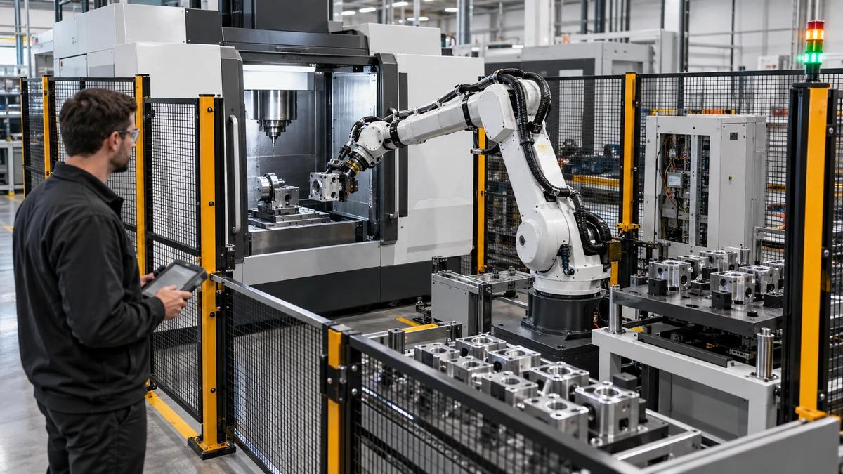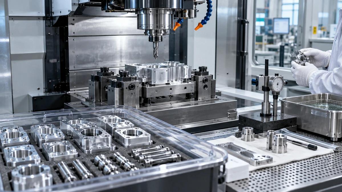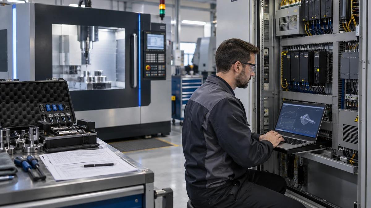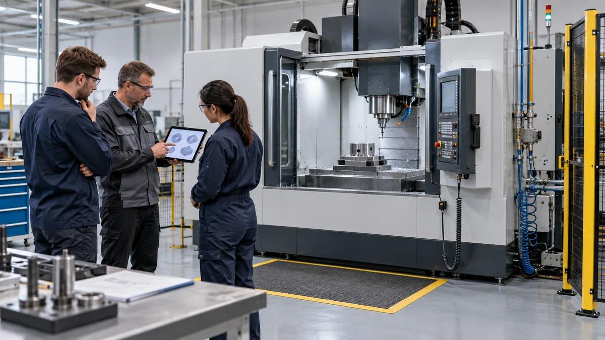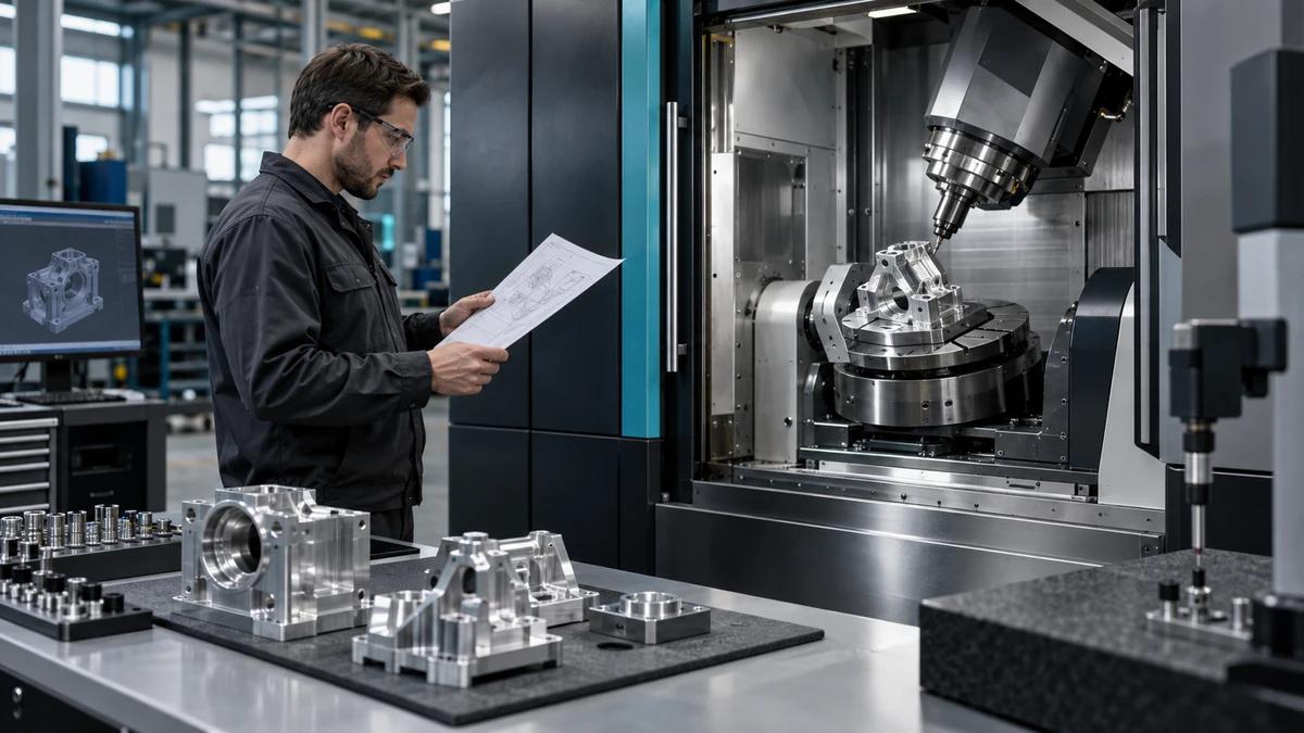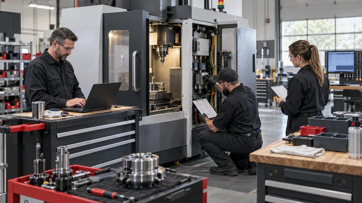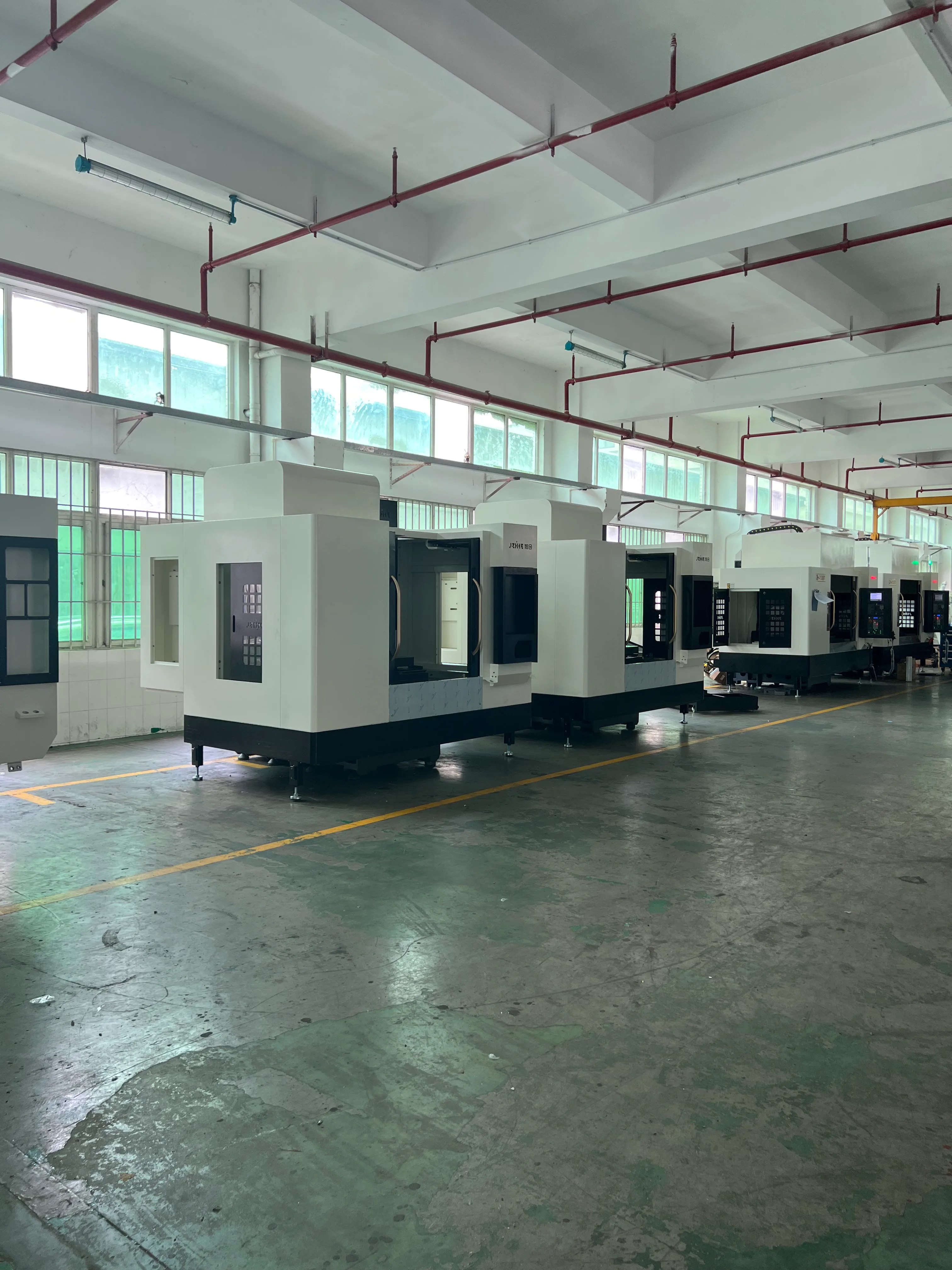
CNC machine hydraulic system selection begins with a sequence of tasks, not a horsepower rating. A workholding clamp may hold force for minutes with almost no flow. A tool-change cylinder may move for a fraction of a second. A pallet changer, tailstock, brake, or fixture may demand pressure at a different moment. If those duties are mixed into one average, the power unit and service plan can look reasonable while failing at the exact instant the machine needs them.
For a Zhihe CNC project, send the installation country, machine configuration, fixture or automation plan, required functions, operating sequence, environment, maintenance capability, and applicable local requirements. Zhihe CNC can confirm the machine-side interface for the selected configuration. The buyer's qualified hydraulic and safety team remains responsible for the final system design, installation, and compliance.
Start With a Duty Cycle, Not a Pressure Label
List every hydraulic function and describe what it does. Include whether it positions, clamps, releases, brakes, indexes, or holds; how far it travels; how fast it must move; how long it holds; how often it repeats; and what happens if pressure or flow is lost.
The duty cycle connects mechanics to the power unit. A clamp that must resist cutting force creates a different requirement from a cylinder that only moves a shield. A tool changer with a short stroke may dominate peak flow, while a clamp may dominate heat because it holds pressure for most of the cycle.
| Hydraulic task | Motion profile to identify | Load condition | Reliability consequence |
|---|---|---|---|
| Workholding clamp | Close, hold, release, repeat | Static force plus process disturbance | Part movement, scrap, or unsafe release |
| Tool-change actuator | Fast stroke, short dwell, return | Inertia and mechanical resistance | Interrupted change or tool damage |
| Pallet or indexer | Accelerate, index, lock | Load torque and position demand | Lost position or obstruction |
| Tailstock or support | Approach, contact, hold | Workpiece mass and thermal change | Deflection or unstable support |
| Brake or safety function | Apply, hold, release | Stored energy and stopping duty | Loss of holding or recovery hazard |
This table is a selection input, not a circuit design. The responsible hydraulic engineer should determine pressure, flow, valve behavior, and protection for the actual machine.
Separate Clamp, Tool-Change, and Axis Duties
Different functions should not be hidden inside one demand figure. A clamp may need pressure to remain stable while the cutting process pushes against the part. A tool-change cylinder may need a quick flow pulse, but only briefly. An optional axis brake or heavy fixture may need controlled release and a safe state after power loss.
Mark simultaneous events. If two clamps, a tool change, and a pallet lock can operate together, the power unit and accumulators must be reviewed for that combined state. If the sequence prevents them from overlapping, record the proof in the control documentation.
Also record what is not hydraulic. Electric actuators, pneumatic clamps, mechanical locks, springs, and counterweights may be better for a specific task. CNC machine hydraulic system selection should not expand hydraulic scope merely because an oil circuit already exists.
Plot Force and Pressure Through Travel
Pressure at the pump is not the pressure at the work. Losses occur through valves, fittings, hose, filtration, coolers, and long runs. Mechanical advantage changes through a linkage or wedge. The required pressure may change as the cylinder extends, the part seats, or the clamp rotates into position. A CNC machine hydraulic system selection review should use this travel condition instead of one static gauge value.
Create a simple travel plot for each critical function: position, required force, available pressure, flow demand, and time. The plot helps engineering see whether the limiting condition occurs at the beginning, middle, or end of the motion. It also exposes a design that has enough static pressure but insufficient dynamic response.
Pressure spikes can result from deceleration, load reversal, valve closure, or an external force. The responsible designer should review them with the actual circuit and component data. A gauge reading taken after the event may tell very little about the spike that caused the damage.
Match Flow to the Shortest Required Motion
Flow determines speed. A small cylinder that moves quickly can demand more instantaneous flow than a large cylinder that moves slowly. The pump, valves, lines, and accumulators must be evaluated together at the required velocity, not only at maximum rated pressure.
There is often a tradeoff between speed and controllability. A very fast approach may save cycle time but create impact, noise, heat, or position error. A slow approach may be gentler but increase cycle time and thermal load. Ask the process owner what the motion must achieve and where a soft transition belongs.
Measure a representative cycle when possible. The commanded cycle, the actual pressure trace, valve commands, and motion profile can reveal whether the assumed duty matches the installed behavior. Use approved instrumentation and safe test conditions.
Understand Continuous and Peak Heat
Hydraulic heat comes from pressure drop, throttling, relief flow, friction, and inefficient operation. A system that holds pressure for long periods may produce heat even when the actuator is not moving. A fast cycle may create a short temperature rise that is difficult to see with an average reading. CNC machine hydraulic system selection must account for both the long hold and the short peak.
Record the oil temperature at the reservoir, return line, and representative component locations. Track the ambient condition and the operating mode. A hot machine at the end of a summer shift and a cold machine at winter startup can have different viscosity, response, leakage, and filtration behavior.
The cooler should be selected for the heat load and the site, not copied from a similar machine. Air-cooled, water-cooled, and combined arrangements bring different utility, condensation, cleaning, and leak risks. The maintenance team must be able to inspect and service the chosen arrangement.
Treat Contamination as a Design Input
Contamination can enter during assembly, through a damaged cylinder rod seal, from a dirty fill, through a breather, or from internal wear. It can reduce valve response, accelerate pump wear, and block small passages. The target cleanliness level, filter location, and monitoring method should be part of the approved design.
ISO 4406:2021 provides a method for reporting the quantity of solid particles in hydraulic fluid. Use the correct edition and the machine builder's specification. A cleanliness code is not a substitute for good assembly, flushing, sealing, and service practices.
Decide where filtration is installed and who can service it. A filter that is difficult to reach may stay in place too long. A filter with no differential-pressure indication may become a source of flow loss. Record the baseline oil condition and the action that follows an out-of-limit result.
Decide Whether an Accumulator Earns Its Place
An accumulator can store energy, smooth pressure pulsation, or supply a short high-flow event. It can also introduce stored energy, precharge requirements, a service procedure, and additional failure modes. It should solve a named duty-cycle problem rather than appear as a generic upgrade.
| Power-unit choice | Useful when | What must be checked | Service boundary |
|---|---|---|---|
| Fixed-displacement pump | Demand is steady and simple | Heat, unloading, and pressure control | Pump, valve, and cooler |
| Variable-displacement pump | Flow demand changes significantly | Response, minimum flow, and control stability | Compensator and control |
| Multiple pump sections | Tasks conflict in pressure or flow | Isolation and simultaneous demand | Section ownership |
| Accumulator-assisted circuit | Short peaks or stored-energy needs are defined | Precharge, volume, isolation, and safe release | Inspection and energy control |
| Dedicated fixture unit | Fixture scope differs from machine scope | Utility, controls, and maintenance ownership | Clear handoff |
The selected arrangement should state what happens during a pump stop, pressure loss, or service isolation. ISO 4413 addresses hydraulic fluid power systems on machinery. The applicable edition and national requirements remain part of the buyer's approval.
Select Components Around Service Boundaries
Pumps, motors, valves, manifolds, cylinders, hoses, filters, coolers, gauges, and sensors form a system. A high-quality component can still perform poorly if the surrounding circuit is wrong. Match pressure rating, flow, temperature, fluid compatibility, duty, mounting, and environment.
Keep service boundaries visible. Which items are inside the machine, which are on the fixture, and which are supplied by the buyer? Who owns the first connection, the drain line, the cooler utility, and the spare parts? A hydraulic schematic without this ownership map creates arguments when service is needed.
Use guarded, accessible, and correctly supported lines. Avoid routing hose near hot surfaces, sharp edges, moving members, or walkways. Follow the component manufacturer's instructions and local requirements for installation and protection.
Match Oil and Seals to the Environment
Fluid choice affects viscosity, seal material, filtration, fire behavior, disposal, and service intervals. The machine builder's specification and the site's operating temperature range should guide the selection. Do not substitute a different oil because it is available in the maintenance store.
The environment also matters. High humidity, washdown, dust, salt, outdoor temperature, and food or medical restrictions can change the enclosure, coating, breather, drain, and seal strategy. If the application has special cleanliness or material constraints, state them before the circuit is frozen.
Document the approved fluid, seal kit, contamination target, and compatibility with every wetted component. Keep evidence for any alternative fluid or additive. A short-term compatibility assumption can become a long-term leak or warranty problem.
Define Quality and Acceptance Tests
Quality evidence should reflect what was actually built. Useful records may include component traceability, pressure and leak tests, function checks, safety checks, oil cleanliness, alarm verification, and a signed configuration list. Those records are also the proof that CNC machine hydraulic system selection assumptions were carried into the delivered machine. The exact test depends on the machine, risk, and applicable requirements.
Do not invent a certification or test result for Zhihe CNC. Ask what documentation the selected machine and component scope includes, then compare it with the buyer's acceptance plan. If a third-party inspection or special test is required, define its scope, standard, witness, and responsibility.
For critical clamps, brakes, or fixtures, verify that the safe state is understood. A hydraulic release may be the intended state or a hazard depending on the design. The employer's risk assessment and energy-control procedure should govern service and recovery.
Plan Maintenance and Spare Strategy
Maintenance should be designed into the selection. Record filter access, oil sampling points, drain location, breather condition, cooler cleaning, hose inspection, accumulator service, and instrument calibration. Define who can isolate the circuit and how stored energy is released.
Spare parts should follow consequence. A failed filter may stop production, while an uncommon valve can create a long wait. Ask the supplier for recommended spares and lead-time assumptions, but do not promise a universal stocking level. Use the machine's duty, local support, and downtime cost to set the buyer's plan.
Keep a service log for pressure settings, oil additions, filter changes, temperature trends, and abnormal noise or leakage. A trend is often more useful than a single result because hydraulic degradation can be gradual.
Compare Machines on the Whole Hydraulic Service Life
Two machines can have similar cylinders and pumps but very different service burdens. One may use a common manifold and easy-to-reach filter; another may hide components behind guarding or require special tools. One may have clear pressure monitoring; another may require a temporary gauge. A complete CNC machine hydraulic system selection comparison includes these lifecycle differences.
| Comparison area | Question for the supplier | Buyer evidence | Lifecycle effect |
|---|---|---|---|
| Function fit | Does the circuit match the named duty? | Duty-cycle and acceptance record | Scrap, cycle time, and reliability |
| Thermal design | What heat load and environment were assumed? | Cooling and temperature data | Oil life and stability |
| Contamination control | What cleanliness and filtration are specified? | Sampling and filter records | Valve and pump wear |
| Safety and isolation | How is stored energy managed? | Approved procedure and training | Service risk |
| Service access | Can maintenance reach filters and drains? | Layout review | Downtime and labor |
| Spare strategy | Which items are long lead or special? | Recommended list | Recovery time |
Use the same comparison structure for a standard machine, an OEM variant, and an ODM project. A custom circuit is not automatically better; it is justified when the duty, environment, or interface cannot be handled by a proven arrangement.
Ten Buyer Questions About CNC Machine Hydraulic System Selection
Should I choose the pump before the cylinders?
No. Define the tasks, loads, speeds, hold times, simultaneity, and safe states first. The pump and valves follow from the complete duty cycle.
Can pressure alone describe a clamp?
No. The clamp also needs adequate flow to close, stable pressure to hold, and a defined release behavior under normal and fault conditions.
How do I know whether an accumulator is needed?
Use it when a named peak-flow, pulsation, or stored-energy function requires it. The precharge, volume, isolation, and service procedure must then be defined.
Is higher oil cleanliness always better?
Higher cleanliness can reduce wear but may increase treatment cost and service burden. Select the level required by the components and process, then maintain it with evidence.
What causes hydraulic overheating?
Pressure loss, relief flow, throttling, friction, duty cycle, ambient conditions, and cooler condition can all contribute. Measure the actual system rather than assuming one cause.
How should a hydraulic failure be handled?
Use the machine's risk assessment, alarm response, and employer's energy-control procedure. Do not release stored pressure or restart a function without authorization.
Can a fixture have its own hydraulic unit?
Yes, if the scope, controls, utilities, safety, and maintenance ownership are clearly documented. A separate unit can simplify some tasks and complicate others.
What fluid should be used?
Use the fluid specified for the selected components and environment. Confirm compatibility and do not substitute by color, viscosity, or local availability alone.
What should be inspected during commissioning?
Inspect pressure, flow, leaks, temperature, cleanliness, alarms, safe states, service access, and the installed configuration against the approved documents.
What should I send to Zhihe CNC?
Send the machine model, fixture and automation plan, function list, duty cycle, environment, utility limits, local requirements, and maintenance strategy.
Freeze Selection After the Duty Review
Review the Zhihe CNC machining-center portfolio and the company and manufacturing profile. Then use the engineering contact route to share the functions, cycle, environment, and ownership map.
The useful output is not a prize-winning schematic. It is a configuration in which every hydraulic task has a defined load, duration, failure state, service owner, and acceptance record. A controlled CNC machine hydraulic system selection makes those choices visible before the machine reaches the floor.