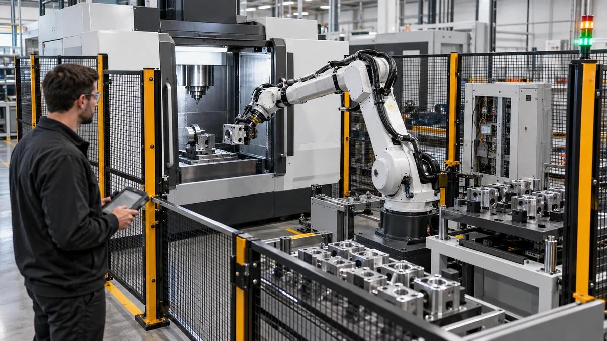
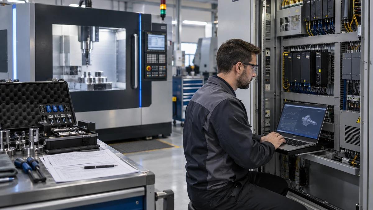
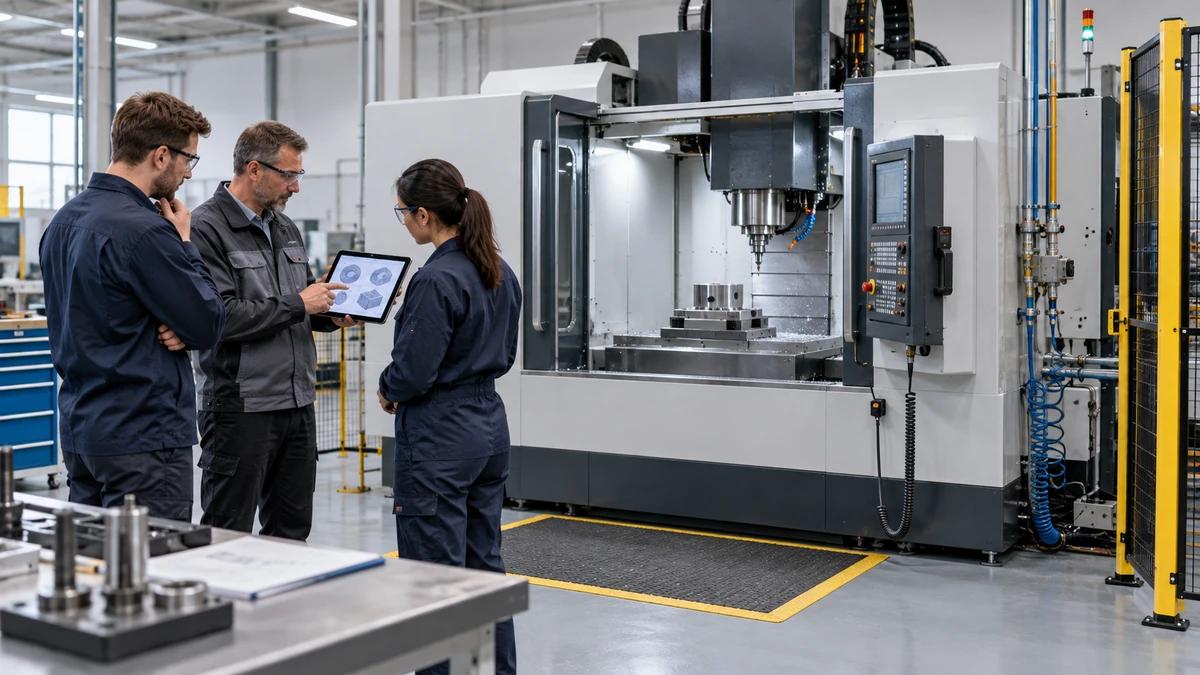
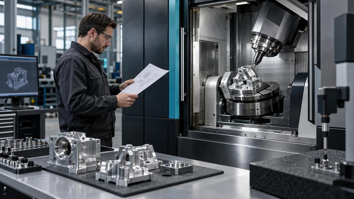
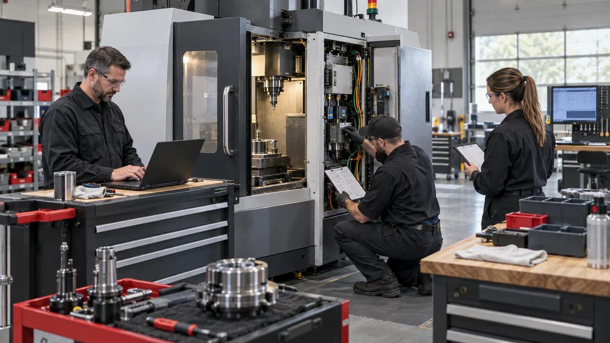
A CNC machining center for gearbox housings should be tested along the torque path, from input bearing seats through internal shaft relationships, split or cover faces, lubrication features, and mounting datums. Zhihe CNC turns that path into an acceptance relay with evidence at each handoff.
The method supports defined cast or fabricated cases, covers, carriers, and related housings. It does not prove gear performance, noise, load rating, lubrication behavior, or service life from housing machining alone; the responsible product team must connect those outcomes to design, components, assembly, testing, and use.
Hand the Baton to the Input Bearing Seat
Index revision, material, blank route, lot, stock, input and output bearing seats, intermediate axes, split or cover joint, mounting feet or flange, dowels, threads, oil passages, seal features, inspection, volume, and downstream assembly. Identify which relationships carry the most consequence.
Zhihe CNC recommends starting with the torque path rather than the longest dimension. The machine choice should protect the datum and feature chain that the gearbox assembly actually uses.
Lay Out the Torque-Path Relay
| Relay leg | Relationship to preserve | Proof |
|---|---|---|
| Input seat | Axis to primary datum | Bore and location report |
| Intermediate seats | Center and axis relationships | Multi-feature inspection |
| Output seat | Axis and face relation | Final bore evidence |
| Split face | Joint geometry and pattern | Face and hole report |
| Mounting | Case to equipment interface | Datum release |
| Lubrication | Passage and seal support | Feature and cleanliness record |
A dropped baton is an unresolved datum, transfer, or inspection link.
Interrogate the Case Blank
Review casting draft, parting, cores, gates, risers, scale, repairs, stress relief, distortion, hardness, stock allowance, wall variation, identification, and preservation. Compare actual stock at locator, bore, split-face, and mounting regions.
A CNC machining center for gearbox housings cannot create missing wall or stock. Define blank holds before cycle targets pressure the team to machine questionable material.
Select the Main Case Orientation
Compare access to bearing seats, split face, mounting, internal cavities, lubrication features, and inspection. Include center of gravity, loading, support, clamp sequence, chip retention, tool reach, spindle clearance, doors, pallets, and recovery.
Control the Split-Face Contract
| Contract item | Process condition | Release question |
|---|---|---|
| Datum preparation | Clean and protected contacts | Is location repeatable? |
| Face machining | Tool, path, heat, support | Is the joint condition controlled? |
| Dowel features | Sequence and tool state | Can halves relocate? |
| Bolt pattern | Position and thread route | Can assembly proceed? |
| Inspection | Restraint and alignment | Is the method reproducible? |
The contract applies to one-piece covers and split cases according to the actual design.
Make Bearing Relationships Survive the Setup
Define diameter, form, axis, center distance, face relation, spacing, and surface characteristics according to the controlled drawing. Agree which features stay in one orientation and how any transfer is re-established.
Zhihe CNC recommends a representative boring or finishing tool assembly with declared holder, projection, runout, condition, parameters, thermal state, and measurement. One short rigid demonstration tool cannot approve the longest production access.
Give Internal Cavities a Chip Exit
Map pockets, ribs, galleries, fixture ledges, tool approach, coolant direction, through-tool supply, air where permitted, recutting, washdown, conveyor, filtration, tank service, and safe cleanout. Observe chips after each important rotation or transfer.
Internal chips can interfere with tools, sealing, lubrication passages, inspection, and assembly. Count clearing, cleaning, and verification time in accepted-output capacity.
Protect Lubrication and Seal Features
Document drilled passages, galleries, ports, threads, plugs, grooves, seal lands, drains, breathers, and intersections. Define tool condition, depth, breakthrough, burr control, flushing, cleaning handoff, protection, and inspection.
Do not infer lubrication-system performance from the presence of holes. The machining file should state precisely which geometry and handoff conditions were demonstrated.
Run a Torque-Path Acceptance Relay
Freeze case revision, material, blank lot, fixtures, tools, programs, controller state, coolant, thermal sequence, inspection, sample size, limits, exceptions, and retest. The ISO 10791 series reference gives machining-centre test context. The buyer's relay must expose the critical bearing and mounting relationships.
Use repeated loading and preserve actual inspection files.
Keep Safety Inside Every Handoff
The ISO 16090-1 search reference offers safety context for machining centres. Responsible teams must assess heavy or irregular blanks, lifting, workholding, tools, doors, interlocks, ejection, chips, coolant, access, maintenance, cleaning, and recovery under local requirements.
No schedule or acceptance target authorizes bypassing protection.
Rehearse a Cover or Fixture Replacement
Remove and reinstall a controlled cover fixture, case fixture, pallet, or replaceable locating element using the approved method. Record cleanliness, identifiers, wear checks, locating surfaces, fasteners, torque or clamp state, probing, offsets, and verification. Avoid borrowing residual corrections from the earlier installation.
The CNC machining center for gearbox housings should reproduce the defined relationship within the trial limits or open a controlled correction and retest. Preserve both results.
Audit the Relay From Blank to Assembly Handoff
Trace one accepted case and one held case from material and revision through setup, fixture, tools, programs, offsets, thermal state, inspection, deburring, cleaning, marking, disposition, and downstream release. Physical labels and current files should agree.
Measure setup, handling, proving, cutting, tool events, chip clearing, inspection wait, rework, scrap, maintenance, and recovery. Gross spindle time is not a complete lead-time or cost model.
Zhihe CNC recommends trending input, intermediate, and output bearing relationships separately. When one leg changes, investigate its blank stock, fixture contacts, tool assembly, heat sequence, and measurement before adjusting unrelated features.
Reopen affected relay legs after changes to design, blank supplier, material, stress relief, fixture, tool, program, coolant, software, inspection, site, or maintenance. Archive the conditions behind earlier approval.
Challenge the CNC Machining Center for Gearbox Housings With Two Mating States
Choose a representative case and cover, two split halves, or a housing plus a qualified reference interface. Preserve the controlled revision, blank route, datums, fixture, tools, programs, thermal sequence, and inspection methods for both mating states. The trial should expose the joint face, dowels or locating features, fastener pattern, and at least one bearing-axis relationship.
Inspect each state independently before mating so a later assembly does not hide the source of disagreement. Then evaluate the approved assembled or simulated relationship under the buyer's defined restraint and alignment conditions. Record cleaning, protection, handling, temperature, and the exact files used for the decision.
A CNC machining center for gearbox housings should reproduce the contract after a normal tool replacement or repeat loading. Compare face condition, dowel location, bore relationships, manual intervention, and inspection time. Preserve failed findings and define the correction and retest instead of tuning values until the assembly appears acceptable.
At closeout, trace both mating identities from foundry records to disposition. State which gear, shaft, bearing, seal, lubrication, and product tests remain outside the housing trial. The two-state challenge makes the CNC machining center for gearbox housings decision useful without turning dimensional evidence into unsupported system-performance claims.
Archive the two mating states with photographs, fixture revisions, tool assemblies, programs, inspection alignments, temperature, cleaning, disposition, and open conditions. Include the approved replacement and restart route so a later production shift can fully recover the joint and bearing evidence without relying on personal memory or inherited offsets. Name the responsible reviewer and effective date for every released baseline and later revision.
Define What the Torque-Path Trial Cannot Guarantee
The trial cannot guarantee gearbox torque, noise, vibration, lubrication, temperature, efficiency, service life, yield, or payback. A CNC machining center for gearbox housings demonstrates controlled housing evidence under stated conditions. Gears, shafts, bearings, seals, assembly, testing, lubrication, controls, and use complete the system.
FAQ
Why organize the process around torque path?
It connects bearing seats, shaft relationships, split faces, mounting, and lubrication features used by the assembly.
Which housings fit the relay?
Defined one-piece cases, split cases, covers, carriers, and related components can use the method.
Why inspect the blank before machining?
Stock, distortion, hardness, cores, repairs, and wall variation can change location, tools, cycle, and yield.
Must all bearing seats be finished together?
Not always; access and support may require transfers, but every transfer needs controlled relationship evidence.
What is the split-face contract?
It defines datum, face, dowel, pattern, restraint, and inspection conditions that let mating parts assemble consistently.
Why test fixture replacement?
It shows whether the process can recover after normal maintenance or production change without hidden offsets.
Does the trial prove gearbox noise?
No. Noise depends on the entire geared system, assembly, lubrication, controls, loads, and testing.
What time belongs in capacity?
Include setup, handling, tools, chips, cleaning, inspection, rework, scrap, maintenance, and recovery.
When should a relay leg reopen?
Reopen affected evidence after relevant blank, fixture, tool, software, inspection, site, or maintenance changes.
Which gearbox case file starts the Zhihe CNC review?
Send controlled cases, blanks, materials, bearing and face relationships, fixtures, tools, volumes, and inspection plans.
Run the Torque-Path Relay With Zhihe CNC
To evaluate a CNC machining center for gearbox housings, send Zhihe CNC your controlled CAD, drawings, blank route, materials, bearing relationships, split and mounting datums, fixtures, tool assemblies, volumes, cleaning, and inspection route. Review the horizontal machining center range, the Zhihe CNC profile, and the contact route before handing off the first baton.