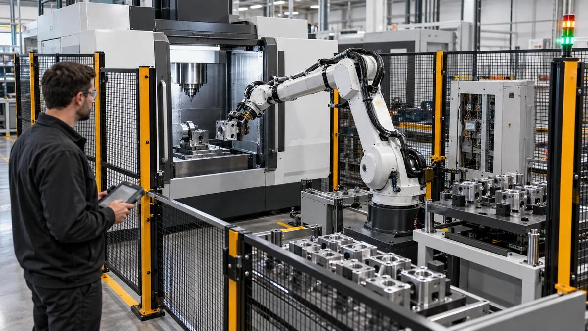
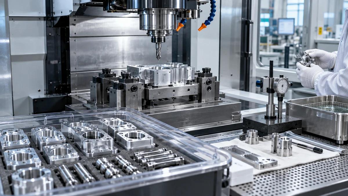
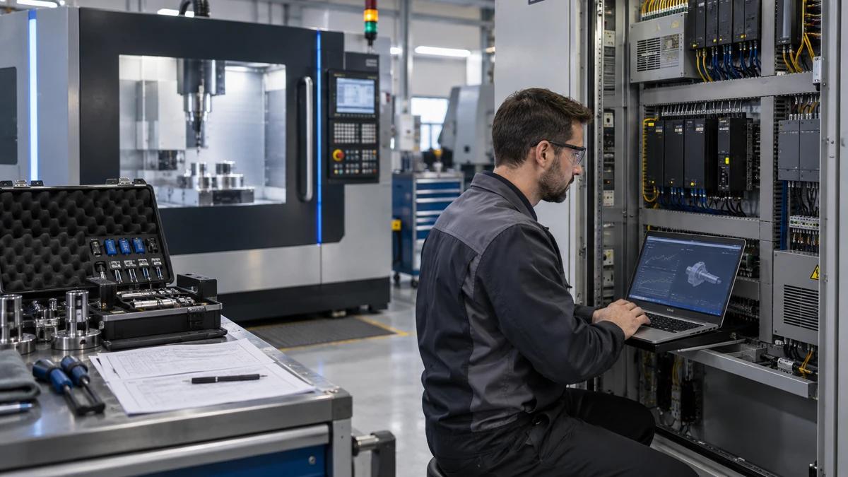
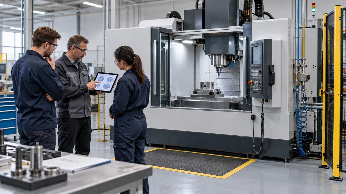
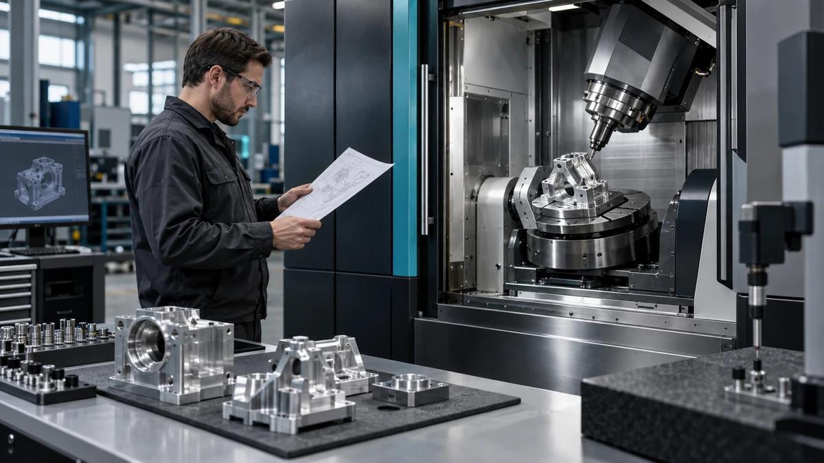
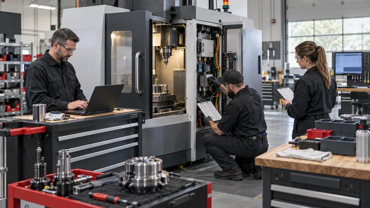
A CNC machining center for motor housings should be tested by making five functional axes agree: bearing alignment, end-face relationship, mounting orientation, cooling-feature location, and the inspection coordinate system. Zhihe CNC maps those axes before choosing setups or machine configuration.
The constellation approach supports defined cast or fabricated housings for motors, generators, drives, and related equipment. It does not convert machining results into claims about electrical efficiency, vibration, noise, thermal performance, or service life without responsible assembly and product testing.
Plot the Housing Constellation
Index revision, material, blank process, lot, stock, maximum envelope, mass, bearing seats, pilot diameters, end faces, feet or flanges, terminal and accessory features, cooling channels or fins, threads, wall-sensitive areas, datums, tolerances, surfaces, volume, and inspection.
Zhihe CNC recommends identifying assembly-critical relationships first. A housing can contain acceptable individual diameters while still creating trouble when bore axes, faces, mounting, and measurement alignment disagree.
Name the Five Axes Before the First Clamp
| Axis | Functional question | Machining evidence |
|---|---|---|
| Bearing axis | Do seats share the intended line? | Bore relationship report |
| Face normal | Are end faces related correctly? | Face-to-axis result |
| Mounting axis | Will the housing install as designed? | Feet or flange location |
| Cooling axis | Are passages and features located? | Feature map |
| Inspection axis | Can results be reproduced? | Datum alignment method |
The five axes may not be literal machine axes; they are a discipline for connecting functional relationships.
Read the Casting or Fabrication Before Location
Review draft, parting, cores, gates, risers, scale, weld state where relevant, distortion, stress-relief history, hardness, stock allowance, repair status, wall variation, and material traceability. Map where the first fixture contacts real stock.
A CNC machining center for motor housings cannot restore missing allowance or cancel uncontrolled blank distortion. Define hold limits and disposition before proving the cutting cycle.
Choose Between One-Line and Relay Machining
Compare a setup that keeps aligned bores and faces in one controlled orientation with a relay that transfers datums across multiple operations. One-line machining may reduce transfers but increase reach, tool, fixture, and chip risks. A relay may improve access and support but needs stronger re-location evidence.
Give Bore Alignment Its Own Evidence Packet
| Packet item | Condition to record | Weak signal |
|---|---|---|
| Tool assembly | Holder, projection, runout | Unidentified boring setup |
| Fixture | Contact, clamp, support | Hidden correction |
| Thermal state | Warm-up and duty | Single cold result |
| Measurement | Alignment, instrument, temperature | Method changes |
| Repetition | Loadings and samples | One best component |
The packet follows the actual components rather than a generic capability number.
Separate Bore Size From Bore Relationship
Define diameter, roundness or form where required, axis location, coaxiality or alignment interpretation, face relation, spacing, and surface. Agree how the drawing requirement is translated into machine process and independent measurement.
Zhihe CNC asks buyers to preserve raw measurement and alignment settings where practical. A summary that only says pass cannot show whether results changed with loading, temperature, tool state, or datum setup.
Make Thin Walls and Clamps Negotiate
Map section thickness, ribs, windows, feet, flange regions, core variation, support, clamp points, force sequence, roughing balance, stress release, semi-finishing, finishing, and free-state measurement. Observe the component during unclamping where deformation is a known risk.
More clamp force is not automatically more stability. The fixture must locate the housing without creating a temporary geometry that disappears after release.
Route Cooling Features Without Losing the Main Axes
Document fins, jackets, drilled passages, threaded connections, drain features, sensor locations, terminal openings, and accessory pads. Include access, remaining walls, intersection, burrs, chips, cleaning handoff, and inspection.
These secondary features can create primary losses when they intersect critical stock, contaminate bores, require a new datum transfer, or consume magazine and inspection capacity.
Run the Axis-Constellation Trial
Freeze housing revision, material, blank lot, fixtures, tools, programs, controller state, coolant, thermal sequence, inspection, sample size, limits, exceptions, and retest. The ISO 10791 series reference provides machining-centre test context. The trial should include repeated loading and the difficult bore-face-mount relationship.
Review accepted components, not only machine motion.
Declare Positioning and Measurement Conditions
The ISO 230-2 search reference supplies positioning-test context. Record foundation, level, temperature, warm-up, axis positions, direction, compensation, equipment, calibration, repeats, and limits. Connect machine evidence to the part trial without treating them as interchangeable.
Rotate One Component Through the Inspection Debate
Give production and quality the same controlled component but ask each team to set up the approved alignment independently. Compare datum preparation, cleaning, restraint, temperature, instrument, program, results, decision rules, and uncertainty response. Resolve any method contradiction before machine acceptance.
The goal is not to make departments compete. It is to confirm that a CNC machining center for motor housings produces evidence that survives a change of operator or measurement station.
Audit the Constellation Across Three Lots
Choose three representative blank lots or production windows. Track stock, fixture contact, tool state, thermal sequence, chips, measurements, manual adjustments, rework, scrap, and accepted quantity. Compare by feature relationship rather than a single overall pass rate.
Trace any alignment trend backward through blank, setup, fixture, tool, machine state, program, temperature, and measurement. Change one meaningful factor at a time where practical, preserve the original result, and define the retest.
Zhihe CNC recommends reviewing handling and protection between machining and measurement. Dirt, nicks, corrosion, temperature, or poor support can distort the evidence after a good cut.
Reopen affected constellation axes after changes to housing, blank supplier, material, stress relief, fixture, tool, program, software, coolant, inspection, site, or maintenance.
Prove the CNC Machining Center for Motor Housings With a Bore-Axis Swap
Select two controlled housings from the same representative blank route. Machine the first with the approved primary orientation. For the second, perform the allowed maintenance-style fixture removal and reinstallation or use a separately qualified fixture instance. Do not transfer unexplained offsets from the first run. Re-establish cleanliness, contacts, clamp state, probing, programs, tools, and thermal sequence through the released method.
Measure the five functional relationships using the same approved alignment and decision rules. Compare bearing axes, face normal, mounting relationship, selected cooling or accessory features, and the inspection coordinate system. Record both raw results and any permitted correction. A passing summary without setup identity or adjustment history is insufficient.
The CNC machining center for motor housings should show whether the process survives a realistic change in fixture state. Investigate differences through blank stock, fixture interfaces, tool assemblies, probe qualification, offsets, machine heat, program, and measurement before changing unrelated variables. Preserve the first finding and link every retest.
Finish with an independent review by production and quality. They should agree which relationships were demonstrated, which remain conditional, and which product-performance claims were outside scope. This bore-axis swap turns the CNC machining center for motor housings comparison into evidence about repeat production, not only one carefully tuned component.
Archive the swap with fixture identities, locator checks, tool assemblies, probe results, offsets, program references, inspection alignments, temperatures, decisions, and open conditions. Add a brief operator handoff so the next shift can reliably reproduce the approved route without relying on the original trial team. Record which spare fixture or locator components must remain readily available for planned maintenance.
Know What the Axis Map Cannot Prove
The map cannot guarantee motor efficiency, vibration, noise, heat transfer, assembly life, cycle, yield, or payback. A CNC machining center for motor housings demonstrates defined geometric and production evidence. Product performance still depends on design, rotor and stator systems, bearings, assembly, controls, testing, and service conditions.
FAQ
Why use five functional axes?
They connect bearing, face, mounting, cooling, and inspection relationships that isolated dimensions can hide.
Must aligned bores stay in one setup?
Not always; one setup and datum relays each carry different access, support, tool, and verification tradeoffs.
Why inspect blank stock first?
Casting or fabrication variation can change location, remaining stock, clamp behavior, tools, cycle, and yield.
What belongs in a bore evidence packet?
Include tools, fixture, machine and thermal state, process, measurement alignment, samples, and raw results.
How can clamping affect thin housings?
Support and force may temporarily deform walls or feet, so free-state behavior can matter.
Do machine positioning results prove bore alignment?
No. They provide related machine evidence; the complete tool, fixture, blank, process, and measurement route still matters.
Why compare two inspection setups?
It tests whether the approved result can be reproduced independently instead of depending on one person's method.
When should the axis map reopen?
Reopen affected relationships after relevant blank, fixture, tool, software, inspection, site, or maintenance changes.
Does the trial prove motor performance?
No. Motor performance requires responsible design, assembly, electrical, thermal, vibration, and service testing.
Which motor-housing inputs belong in the review?
Send controlled housings, blanks, materials, datum interpretations, critical axes, fixtures, tools, volumes, and inspection methods.
Map the Five Axes With Zhihe CNC
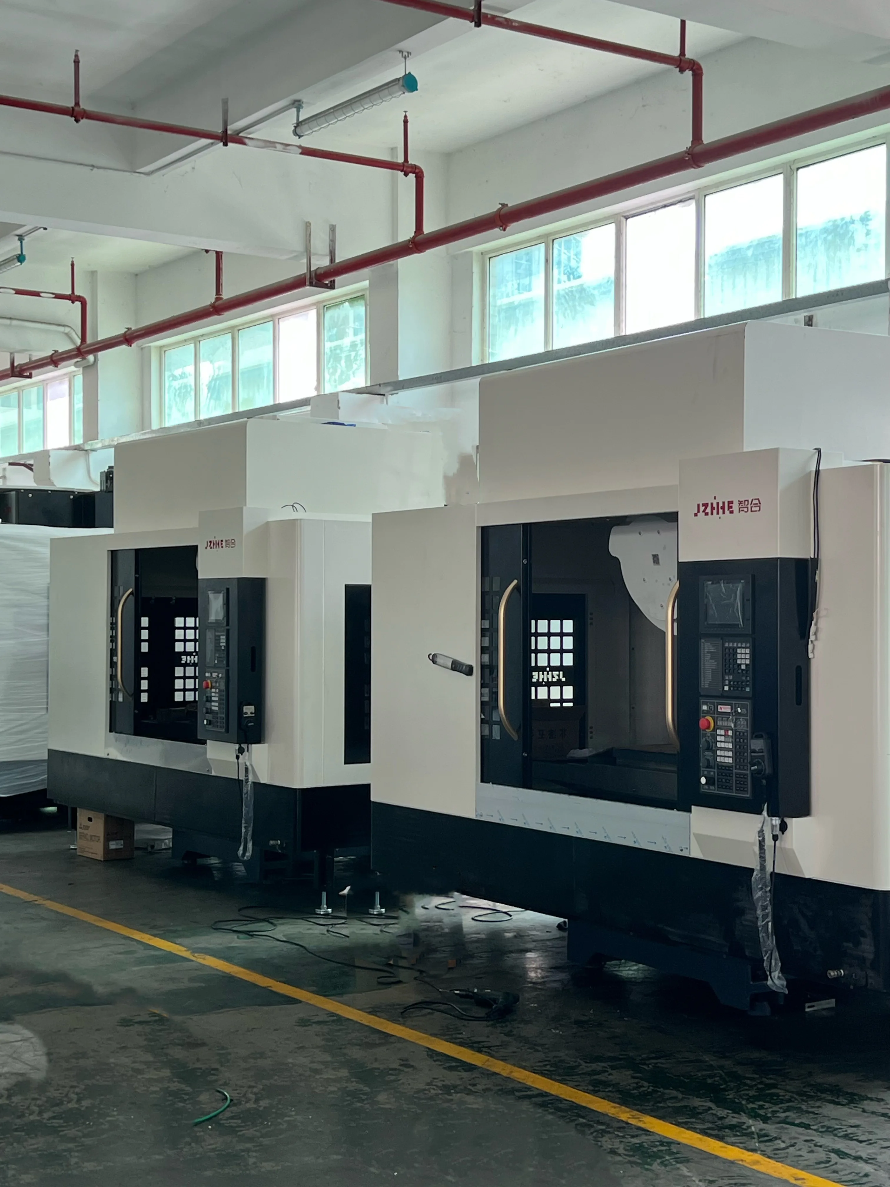
To evaluate a CNC machining center for motor housings, send Zhihe CNC your controlled CAD, drawings, blank route, materials, bearing and face relationships, mounting features, fixtures, tools, volumes, and inspection methods. Review the horizontal machining center range, the product portfolio, and the contact route before freezing the constellation.