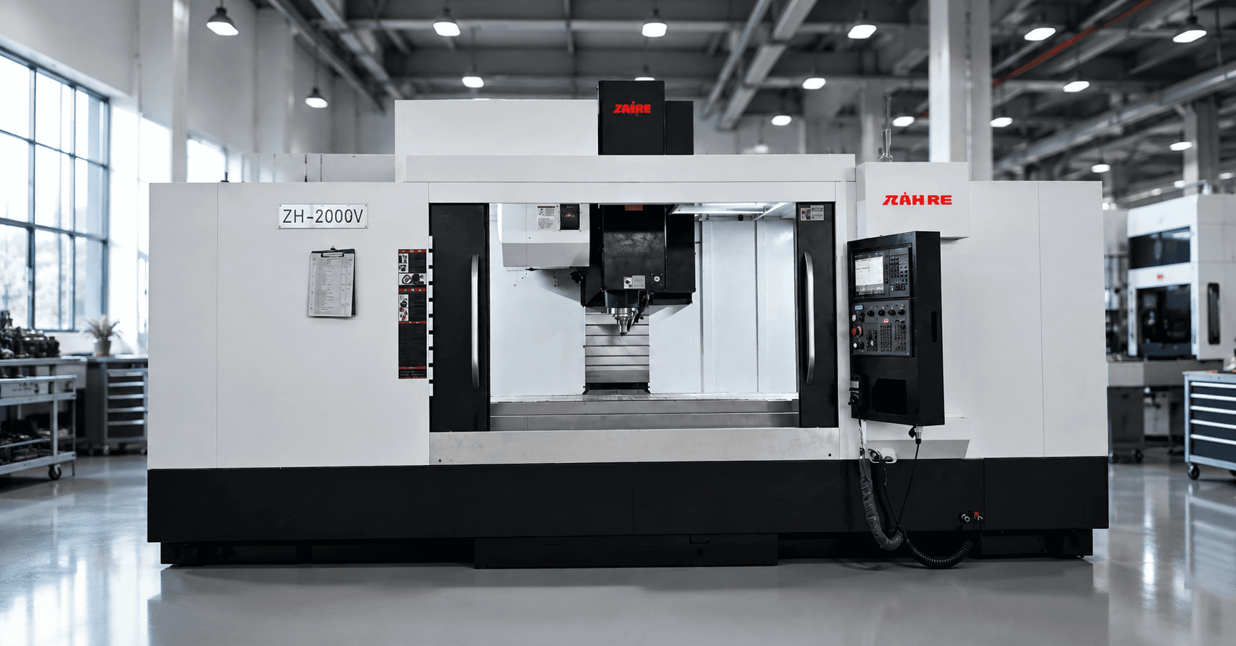
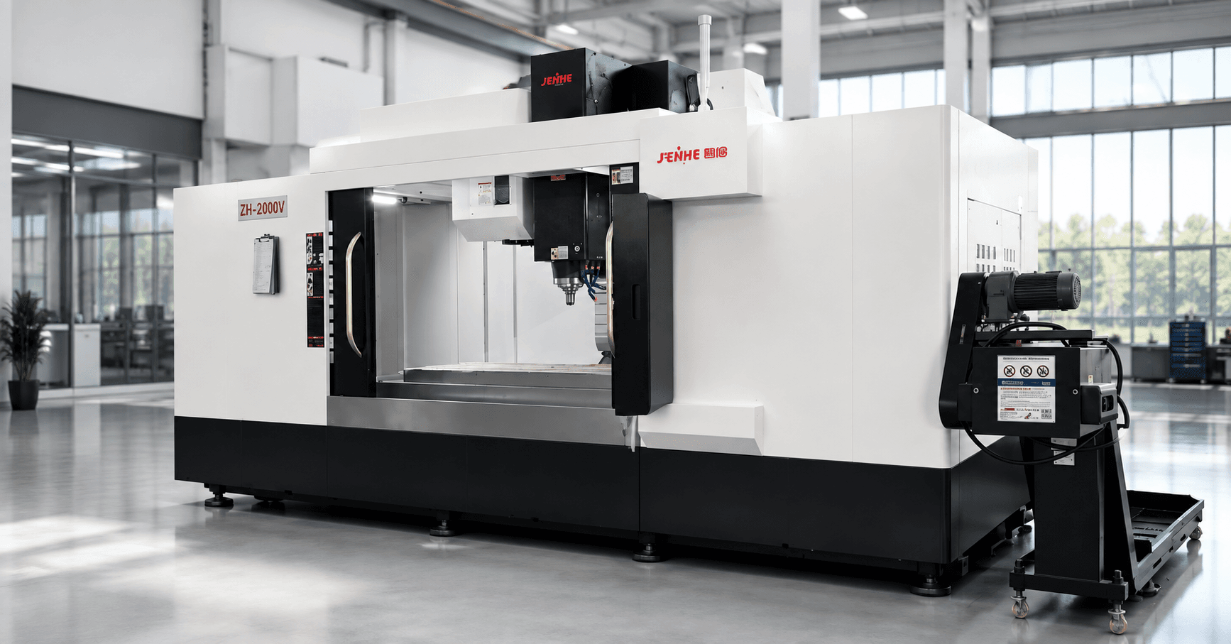
A gantry machining center for large parts should be selected from a coordinate-zone plan of the mounted workpiece, not from raw length and width alone. The plan must include datums, supports, clamps, tool access, thermal behavior, chip flow, inspection positions, loading, and maintenance clearance across every machining zone.
Large structures amplify small planning errors. A part can fit nominal travel yet lose usable reach to fixtures, long tools, crossrail or ram geometry, guarding, probes, clamps, or safe approach. The coordinate-zone method exposes those conflicts before a machine configuration and process route are frozen.
Zone A: Mounted Envelope and Safe Reach
Build a three-dimensional envelope containing the blank, finished part, base, risers, clamps, supports, lifting features, probes, longest tool assembly, spindle head, and required approach paths. Check every extreme feature, not only the overall bounding box. Include door, crane, operator, chip, and maintenance access.
Mark unreachable or marginal areas. A feature near the travel limit may technically fit but leave no safe clearance for tool entry, compensation, probing, or fixture hardware. Confirm the current quoted configuration because model names do not guarantee identical usable space.
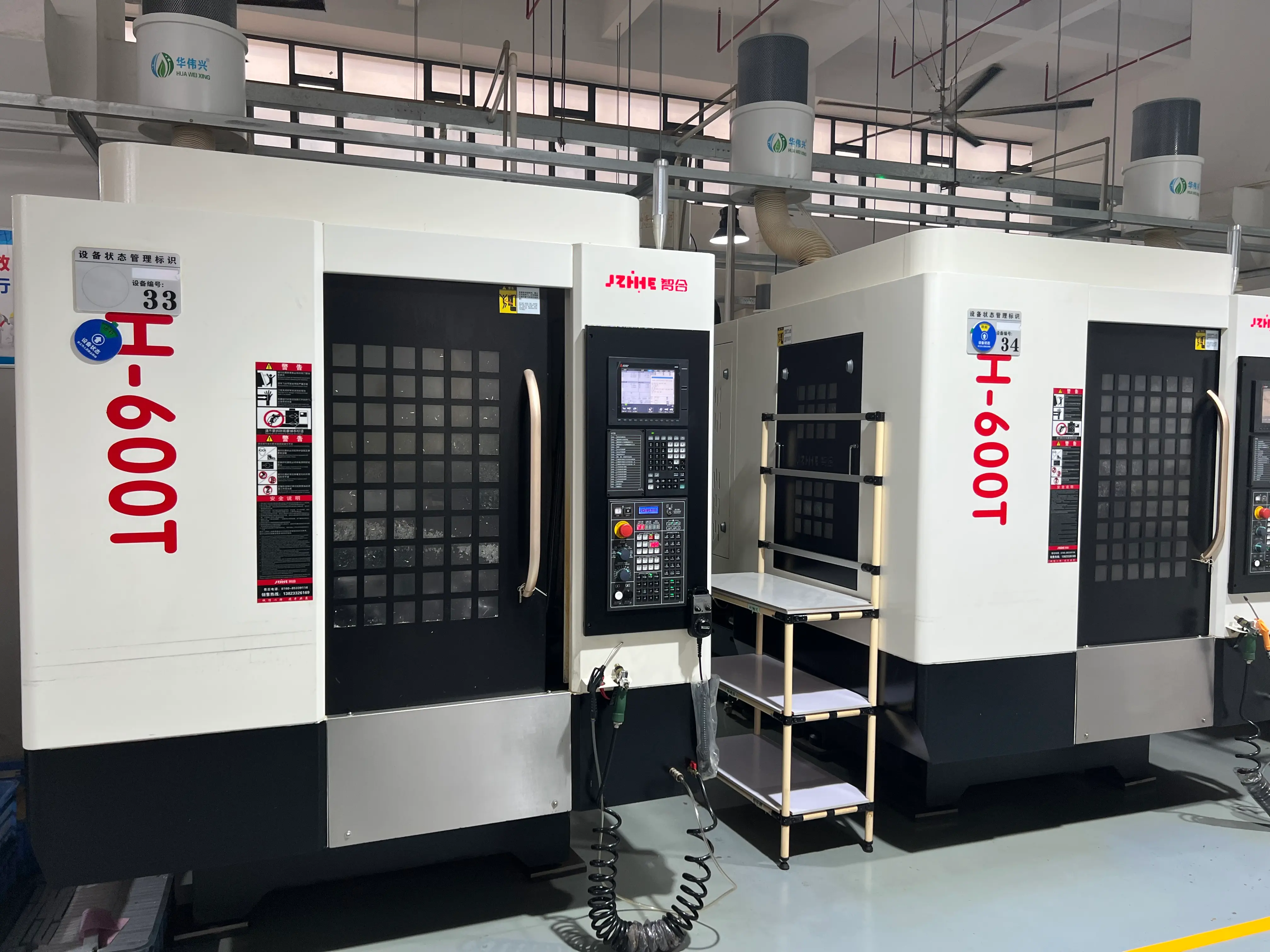
Zone B: Primary Support and Clamp Reactions
Map support points, jack screws, locating pads, clamps, part stiffness, and expected cutting-force paths. Define how the blank is leveled without forcing it into an artificial shape. Large welded, cast, or fabricated structures may carry residual stress or local distortion before machining.
Record support adjustment and clamp sequence. Decide which supports remain fixed and which follow the part as zones are opened. Measure the free or released condition when the customer uses the part without the machining fixture.
Zone C: Datum Migration Across the Part
Create a datum-migration ledger for every repositioning, head orientation, local coordinate shift, probe routine, or secondary setup. Record the source datum, transferred datum, measurement method, expected uncertainty, responsible program, and features affected.
| Transfer event | Risk | Control evidence |
|---|---|---|
| Initial part alignment | Blank bow, twist, uneven stock | Survey and support record |
| Local work offset | Accumulated position error | Probe routine and reference check |
| Head orientation | Angular or tool-center shift | Calibration and verification feature |
| Part repositioning | Lost cross-zone relationship | Common datum and post-move report |
| Final inspection | Temperature and support mismatch | Defined condition and traceable results |
Zone D: Tool Access and Ram Extension
List the deepest pockets, tallest walls, side features, angled surfaces, longest bores, and obstructed faces. For each, record toolholder diameter, gauge length, cutting reach, head position, ram extension, clearance, and expected load. Long reach can reduce rigidity and increase vibration even when travel is sufficient.
Use simulation to check holder, spindle, ram, crossrail, bridge, clamps, and part. Compare alternative orientations or staged stock removal. Keep the heaviest cutting in the strongest available condition where possible, then reserve extended reach for controlled operations.
Zone E: Thermal Sequence and Time
Large parts and machines warm unevenly. Build a time sequence showing spindle duty, heavy cuts, finishing, coolant state, ambient variation, pauses, measurement, and expected batch length. Identify dimensions spanning distant zones and surfaces sensitive to temperature gradients.
Plan roughing and finishing order to reduce drift. Define warm-up, stabilization, compensation limits, and measurement temperature. A gantry machining center for large parts should be tested across a realistic production window, not only on a short cold sample.

Zone F: Chip, Coolant, and Cleaning Paths
Divide the part into chip-generating and chip-trapping regions. Mark deep pockets, ribs, horizontal ledges, fixture cavities, internal passages, and surfaces that can be damaged by trapped chips. Review coolant delivery, enclosure wash, conveyors, filtration, tank access, manual cleaning, and safe chip removal.
Record cleaning time as production time. A fast cut can create a slow, hazardous recovery if chips accumulate around large structures. Plan inspection only after the relevant locating and measurement surfaces are clean.
Zone G: Loading and In-Process Inspection
Define part arrival, lifting points, center of gravity, spreader, slings, crane capacity, route, orientation, temporary supports, and final placement. Add probe access, portable measurement, gauges, reference artifacts, and operator positions. Avoid a plan that requires unsafe climbing or blocked measurement after clamps are installed.
Review the gantry machining center range for architecture context, then compare the complete zone map with the quoted machine drawing and options.
Accept the Process Zone by Zone
- Approve the mounted CAD envelope and loading method.
- Verify supports, clamp reactions, and the initial survey.
- Prove the datum-migration ledger across representative zones.
- Test the longest tool and most extended stable cutting condition.
- Measure cross-zone features after a production-like thermal sequence.
- Record chips, cleaning, inspection, operator work, and interventions.
When a Gantry Is Not the Best Answer
A gantry platform is not automatically the best choice when the part can be divided safely into smaller components, when a horizontal or vertical arrangement gives better access, when the mounted load exceeds the stable configuration, or when volume cannot justify fixtures and process development. Civil works, lifting, transport, utilities, and inspection capability may also dominate the project.
FAQ
Why is raw part size insufficient for selection?
Fixtures, supports, clamps, tools, spindle geometry, access paths, probing, loading, and service space consume the nominal envelope.
What is datum migration?
It is the controlled transfer or recovery of coordinate references across local offsets, orientations, machine zones, or part repositioning.
Should large parts be inspected on the machine?
In-process probing can control the route, but final acceptance must use the agreed method, condition, support, and measurement capability.
How should thermal performance be tested?
Use a time sequence representative of warm-up, cutting duty, pauses, coolant, ambient conditions, and the dimensions that cross distant zones.
Request a Coordinate-Zone Review
To evaluate a gantry machining center for large parts, send the blank and finished drawings, mounted envelope, mass, material, support and clamp concept, lifting plan, deepest features, longest tools, critical cross-zone dimensions, thermal expectations, inspection method, annual volume, and site constraints. Use the contact page to request a zone review, and compare the wider machining center portfolio if another architecture may reduce total risk.