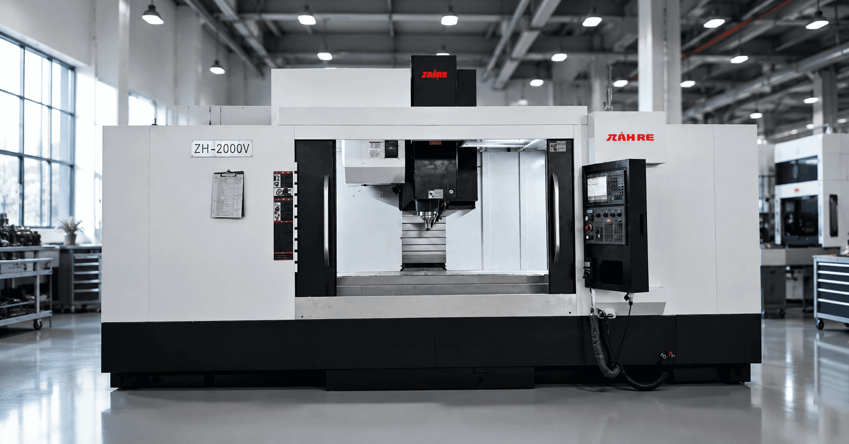
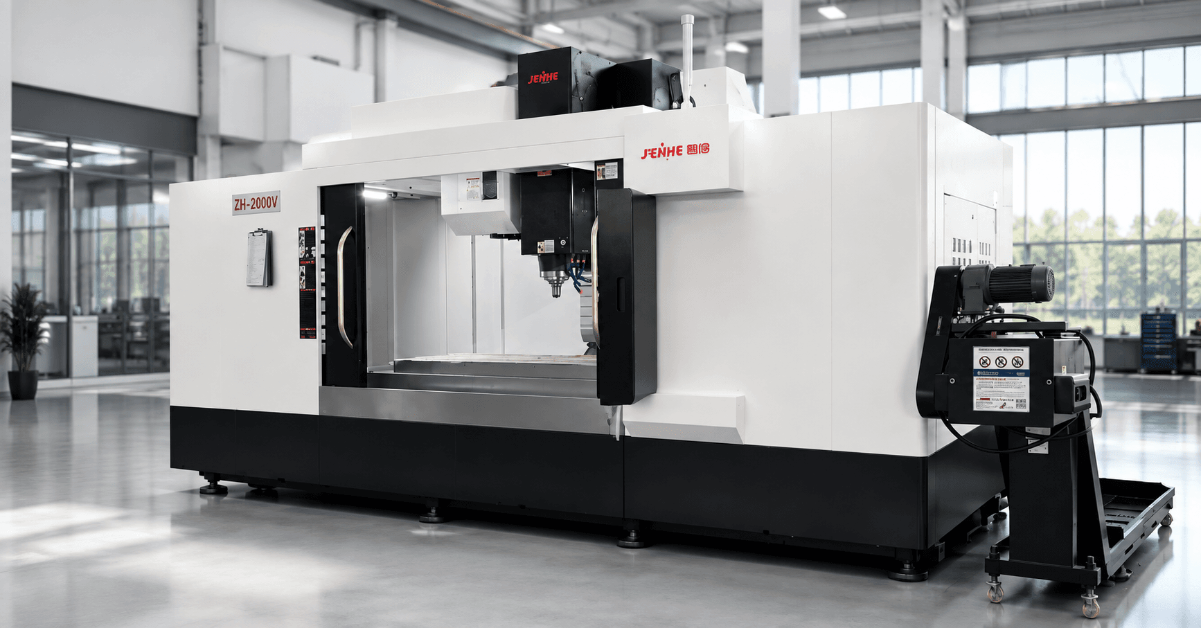
A high rigidity vertical machining center should be selected by proving that the complete cutting system stays stable under the buyer's real load, not by accepting a general claim about castings or machine weight. The workpiece, fixture, toolholder, tool overhang, spindle, axes, foundation, cutting strategy, and thermal condition all influence the result. A rigid frame cannot compensate for a flexible fixture or an unnecessarily long tool.
This guide uses a deflection-risk diagnostic. It starts with the feature that is most likely to move, identifies the load path, converts that risk into a trial-cut plan, and defines the evidence a buyer should request before approving a machine.
Start With a Deflection Risk Map
Do not begin with a machine brochure. Begin with the drawing and mark the features that combine high cutting force, long reach, interrupted engagement, tight geometry, or weak workpiece support. Typical risk areas include deep pockets, tall walls, large face-milling widths, heavy drilling, long boring tools, hard materials, and parts clamped far from the cutting zone.
| Risk source | What can move | Production symptom | Evidence to request |
|---|---|---|---|
| Long tool reach | Tool and holder | Chatter, taper, poor finish, short tool life | Trial with production-length tooling |
| Weak part section | Workpiece wall or rib | Profile error after unclamping | Measurement before and after release |
| Flexible fixture | Clamps, tombstone, base plate | Position drift between cavities or stations | Fixture deflection review and repeat trials |
| Heavy cutting load | Spindle, column, axes, foundation | Size variation and visible vibration | Load-specific roughing and finishing test |
| Thermal growth | Spindle and machine structure | Dimension changes across the shift | Warm-up and time-series measurement |
Separate Static Strength From Dynamic Stability
Static rigidity describes how much a structure deflects under a steady load. Machining is dynamic: cutting teeth enter and leave the material, spindle speed changes excitation frequency, axes accelerate, coolant changes temperature, and chips alter the contact environment. Buyers therefore need evidence of both structural resistance and stable cutting behavior.
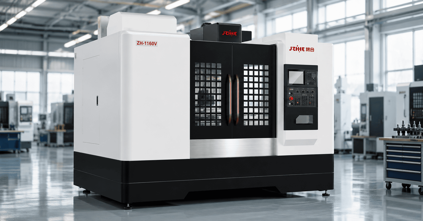
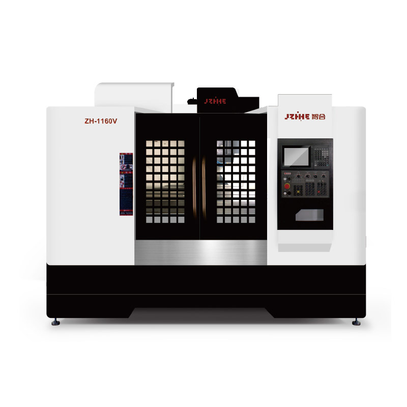
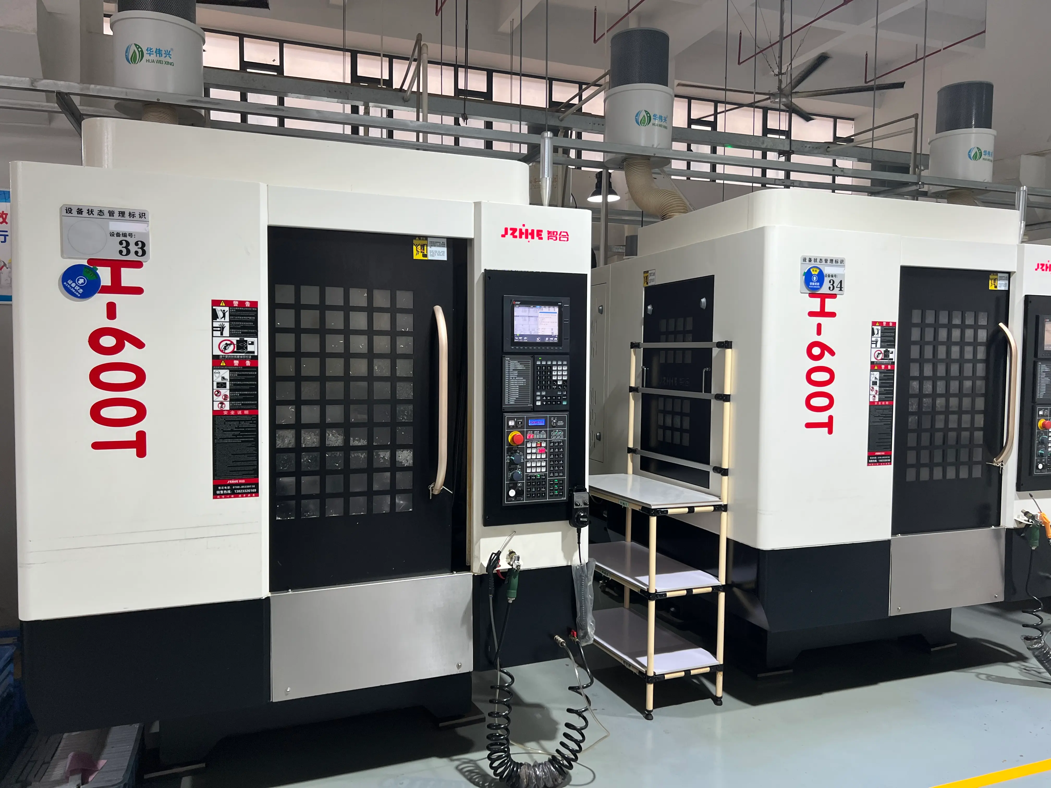
A useful machine review covers casting layout, guideway arrangement, spindle support, axis drive system, table and fixture load, leveling method, foundation needs, lubrication, chip removal, and thermal management. A high rigidity vertical machining center still has to prove stability with the intended fixture and tooling. Zhihe CNC describes its ZH-1160V as a vertical machining center with a high-rigidity structure, precision CNC performance, efficient chip removal, and stable high-speed machining. Those claims are a starting point for application review, not a substitute for a part-specific trial.
Trace the Complete Load Path
- Cutting edge: Confirm insert geometry, tool diameter, flute count, runout, holder interface, and overhang.
- Spindle: Match the expected torque, speed, duty cycle, and tool mass to the operation.
- Machine structure: Review column, saddle, table, guideways, and axis orientation under the intended load.
- Fixture: Check locating support, clamp direction, base thickness, fasteners, and chip contamination risk.
- Workpiece: Identify thin walls, unsupported spans, residual stress, heat concentration, and release distortion.
- Foundation: Confirm floor capacity, anchors or pads, leveling access, nearby vibration sources, and utility stability.
This sequence prevents the common mistake of blaming the machine for variation created by tooling or workholding. It also prevents the opposite mistake: spending weeks tuning a process when the machine is not suitable for the required load.
Test a High Rigidity Vertical Machining Center With a Two-Part Trial
Part A: Stress the roughing condition
Use representative material, tool reach, engagement, coolant, and fixture support. Record spindle load, sound, visible vibration, chip form, cycle time, tool condition, and any feed override. The purpose is not to chase a dramatic material-removal number. It is to confirm a stable production window with acceptable tool life and predictable recovery after interruptions.
Part B: Prove the finishing condition
Finish the critical geometry using the intended tool and datum strategy. Measure flatness, perpendicularity, position, size, surface finish, and any thin-wall movement relevant to the drawing. Repeat the part after warm-up and later in the test window. A single good measurement does not demonstrate a stable process.
Use Acceptance Gates Instead of General Impressions
Write pass/fail gates before the test. Include the drawing features, measurement method, sampling sequence, machine warm-up condition, allowable tool changes, target cycle range, and the person responsible for each record. If chatter appears, document the exact operating point and the change that removed it. If a dimension drifts, determine whether the cause is thermal, tool-related, fixture-related, or structural.
For geometric confidence, discuss laser interferometer, ballbar, leveling, spindle checks, and a controlled trial part. Zhihe CNC's company overview describes machining-center development, manufacturing, inspection, installation, training, and support. Convert those general capabilities into project-specific deliverables.
Compare Process Cost, Not Machine Weight
A heavier machine can be appropriate, but mass alone does not establish process capability. Compare the cost of stable cycle time, tool consumption, fixture complexity, inspection frequency, scrap risk, maintenance access, and future part mix. A machine that needs conservative feeds, repeated spring passes, or frequent offset correction may be more expensive than a higher-specification alternative.
FAQ
Does machine weight prove rigidity?
No. Weight can support stability, but casting design, load path, guideways, spindle support, foundation, tooling, and fixture design determine how the system behaves.
Which operation should be used for the trial?
Choose the operation with the highest combination of cutting force, tool reach, geometry sensitivity, and production consequence. It may be roughing, boring, deep-pocket milling, or finishing a thin wall.
How long should thermal testing run?
Long enough to represent warm-up and the expected production window. The test plan should record time, ambient condition, spindle use, coolant condition, offsets, and measured results.
Should the supplier design the fixture?
Responsibility depends on the project, but the machine, fixture, tooling, and process must be reviewed together. Define who supplies, approves, modifies, and accepts each item.
Request a Load-Specific Stability Review
To evaluate a high rigidity vertical machining center, send Zhihe CNC the drawing, material, blank condition, fixture concept, tool reach, critical tolerances, surface requirements, cycle target, and annual volume. Review the vertical machining center range, then use the contact page to define a trial and acceptance plan.