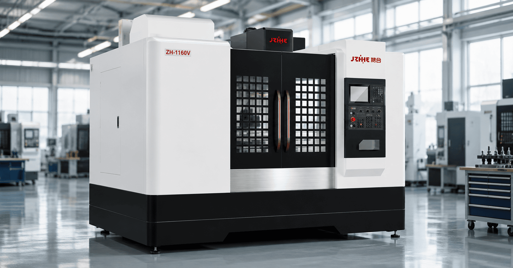
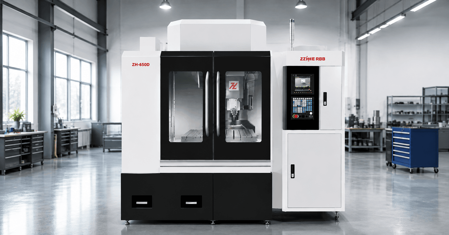
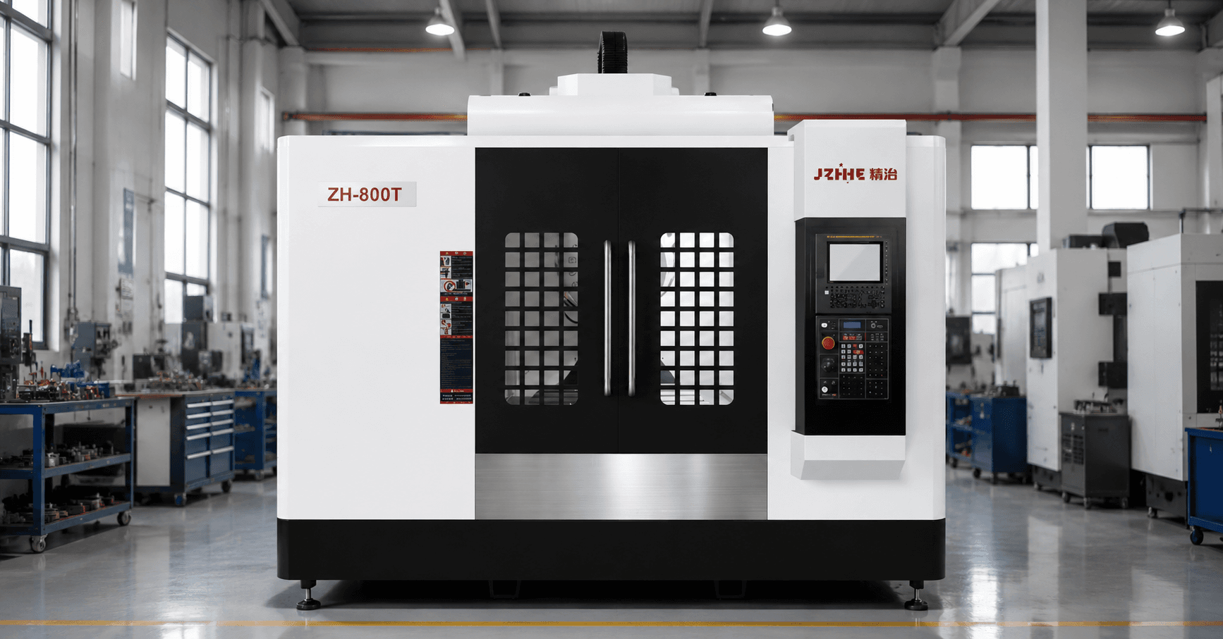
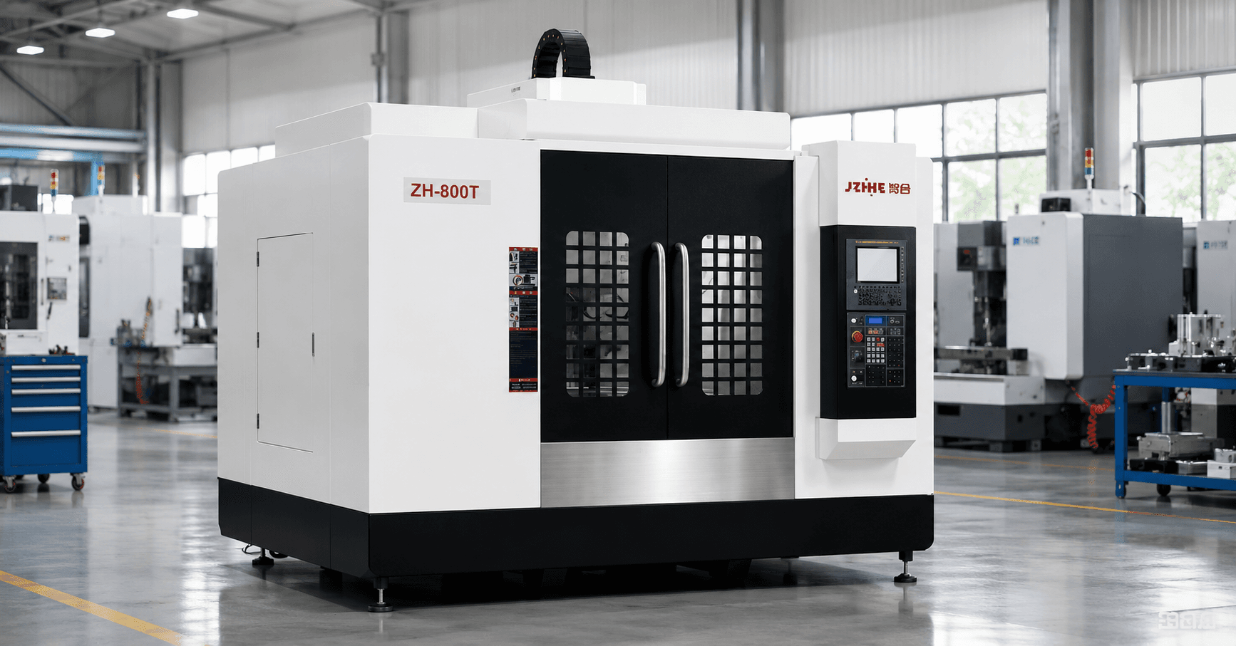
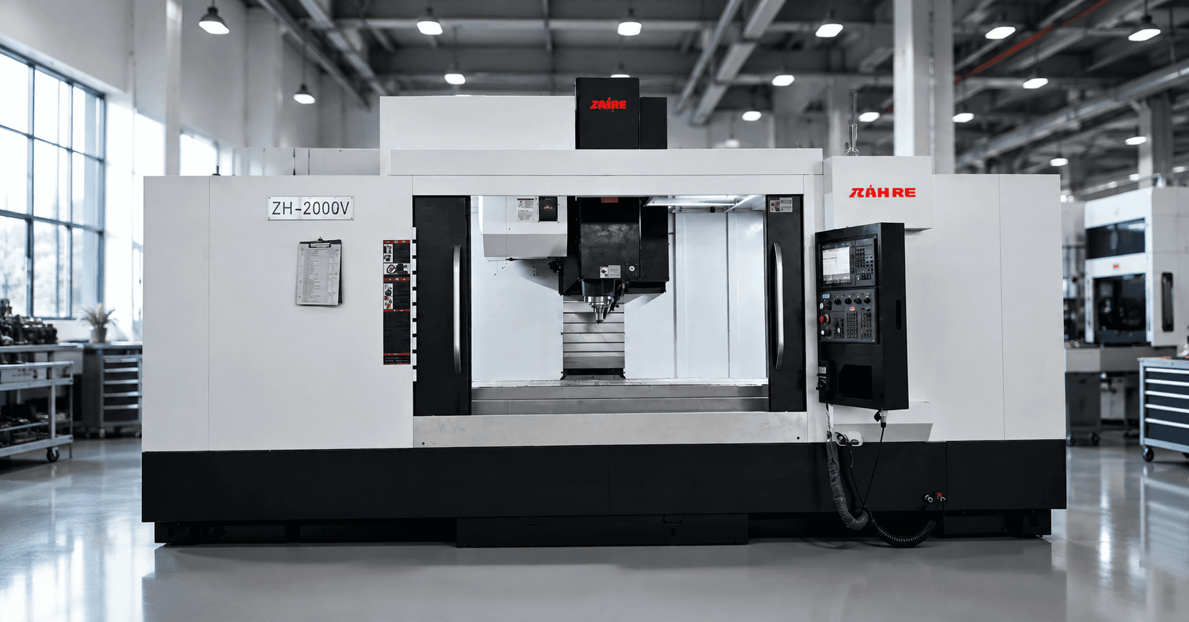
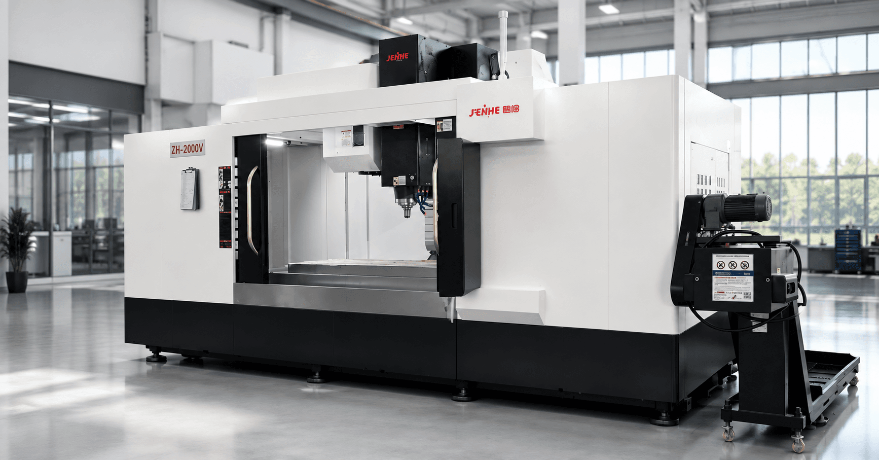
A high speed CNC milling machine should be selected with a frequency-band process map that separates slow structural loads, middle-band axis motion, and high-frequency spindle, tool, and surface behavior. The map connects the part program to the machine instead of treating speed as one number.
It helps buyers identify whether the bottleneck is rigidity, acceleration, look-ahead, spindle duty, tool balance, thermal drift, chips, or inspection.
Band Zero Describes the Part Program
Record material, hardness, blank, features, tools, holders, gauge lengths, engagement, path density, tolerance, surface target, cycle, and inspection. Mark long straight cuts, small corners, dense contours, and frequent direction changes.
The same spindle speed can produce very different motion and stability demands.
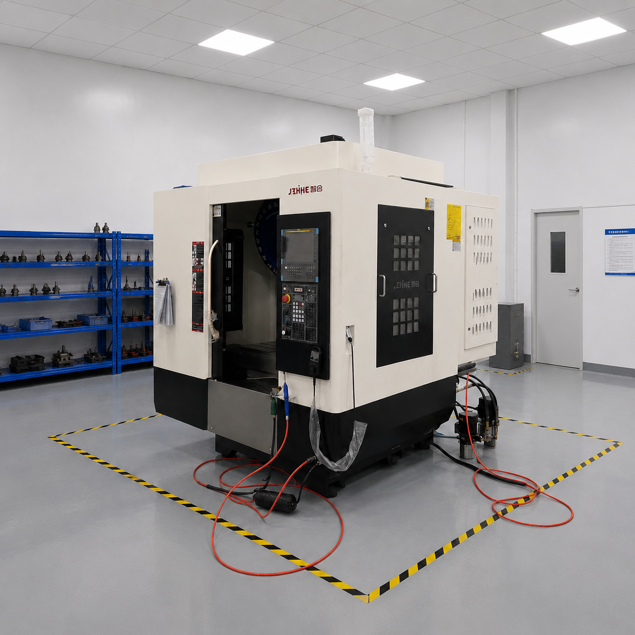
The Low Band Carries Structural Load
Map work support, fixture stiffness, machine structure, guideways, spindle extension, larger tools, cutting force, and sustained material removal. Identify load direction and operating position.
A high-speed label does not remove the need for structural stability during roughing or long engagement.
The Middle Band Controls Axis Motion
Review acceleration, deceleration, jerk control, look-ahead, interpolation, contour tolerance, smoothing, block processing, rotary motion if applicable, and following error. Connect them to path density.
For a high speed CNC milling machine comparison, rapid traverse alone is weak evidence. The relevant question is how motion remains smooth while respecting geometry.
The High Band Protects the Tool Assembly
Check spindle speed range, duty, bearings, cooling, taper, runout, holder, balance, tool diameter, gauge length, collet or shrink fit, pull stud, and replacement condition. Define maximum approved assemblies.
Small errors create larger forces at speed. Tool assembly control is a production discipline, not only a supplier specification.
| Frequency band | Dominant variables | Evidence |
|---|---|---|
| Low | Structure, support, force, duty | Stable removal and geometry |
| Middle | Acceleration, corners, look-ahead | Path-time and contour record |
| High | Spindle, balance, runout, vibration | Tool and finish evidence |
| Thermal | Warm-up, coolant, room, cycle | Condition trend |
| Recovery | Tool, alarm, restart, verification | Controlled return |
Build a Corner-Energy Card
For representative corners, record programmed feed, actual feed, radius, acceleration, smoothing, tool engagement, chip load, vibration, and surface marks. Compare different path strategies.
A slower corner can improve finish and tool life while increasing time. The card makes this tradeoff visible.
Map the Thermal Band
Trace spindle heat, axis motion, coolant, room temperature, warm-up, pauses, tool changes, workpiece temperature, and measurement timing. Use the intended production duration.
Review the milling machining center range, then define a conditioned trial. A short demonstration may not expose drift.
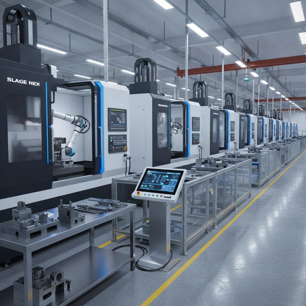
Give Chips and Dust a Band
Estimate chip size, volume, direction, recutting risk, coolant or air, extraction, filtration, wash-down, tank, and cleaning. Fine graphite, aluminum chips, steel chips, and mixed materials need different control.
Chip behavior can limit unattended time and surface quality even when motion is fast.
Inspect Surface and Geometry Separately
Define dimensional features, contour error, cusp, waviness, tool marks, blend lines, burrs, and cosmetic zones. State instruments, lighting, filtering, support, temperature, and acceptance limits.
A surface can look smooth while geometry is wrong, or meet dimensions while visible marks remain. Both need evidence.
Map the Control-Parameter Band
Record contour tolerance, smoothing, look-ahead mode, acceleration limits, feed optimization, spindle control, compensation, and any licensed high-speed functions. Keep approved settings with the program revision.
A parameter change can improve time on one path while damaging corners or surfaces elsewhere. Validate changes on representative features and define who may release them to production. Preserve the previous setting and the inspection result so the team can reverse a change without guesswork.
Run the Three-Band Trial
- Select one structural cut, one dense contour, and one finish-critical surface.
- Use actual holders, tools, CAM, post, and control settings.
- Record commanded and actual path time.
- Track temperature, tool condition, chips, and interruptions.
- Inspect geometry and surface under agreed conditions.
- Define the stable band and approved exceptions.
When Lower Speed Wins
Lower spindle or feed settings can improve tool life, finish, heat, burr control, or process reliability. Maximum speed is not automatically the economic optimum.
High-speed capability creates value when the digital chain, tool assemblies, motion control, and production discipline can use it consistently across normal shifts and tool-life changes.
FAQ
What spindle speed counts as high speed?
There is no universal threshold; material, tool diameter, surface speed, spindle design, and application define useful speed.
Why does programmed feed differ from actual feed?
Acceleration, corners, look-ahead, contour settings, block density, and machine limits can reduce actual motion.
Is balanced tooling required?
Use supplier limits and risk-based tool assembly standards for the intended speed, diameter, length, and holder.
Should coolant always be used?
No. Material, tool, finish, chip evacuation, thermal behavior, and machine design determine the strategy.
Request a Frequency-Band Assessment
To configure a high speed CNC milling machine, send part models, material, tools, holders, gauge lengths, CAM paths, postprocessor, tolerances, surface targets, cycle, coolant or extraction, inspection, and destination. Use the contact page for a process review and consult the motion-time waterfall guide for cycle analysis.