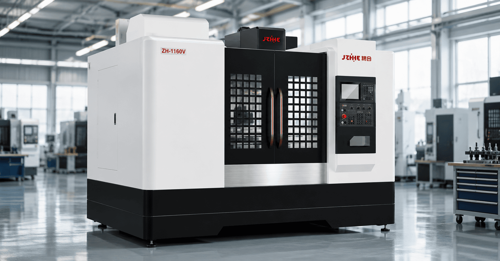
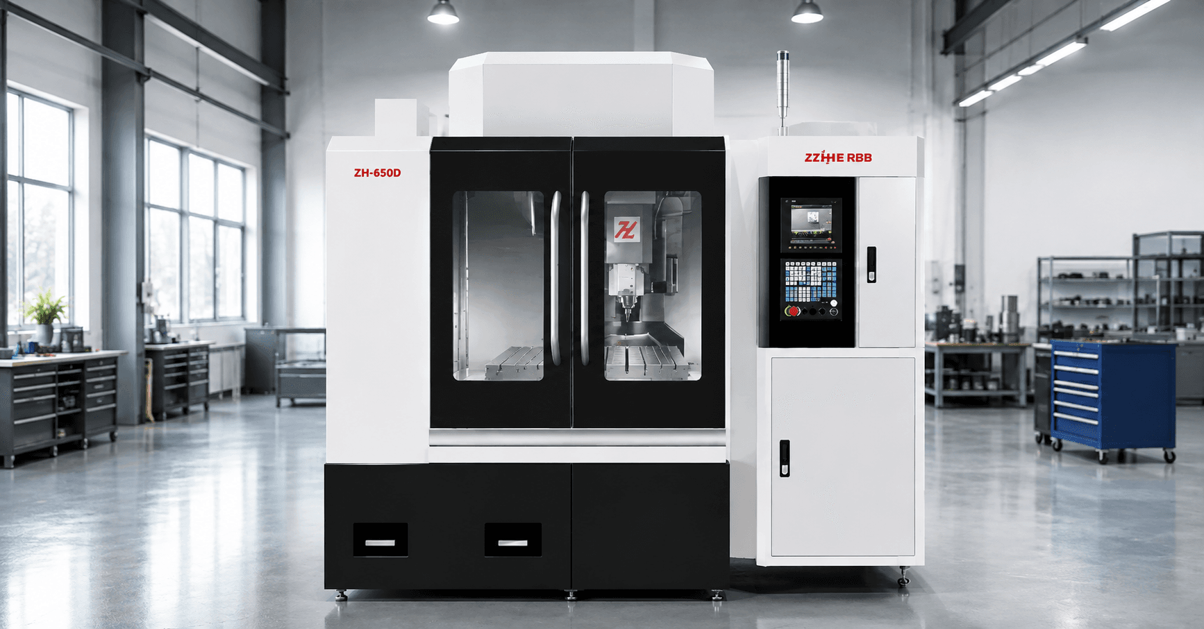
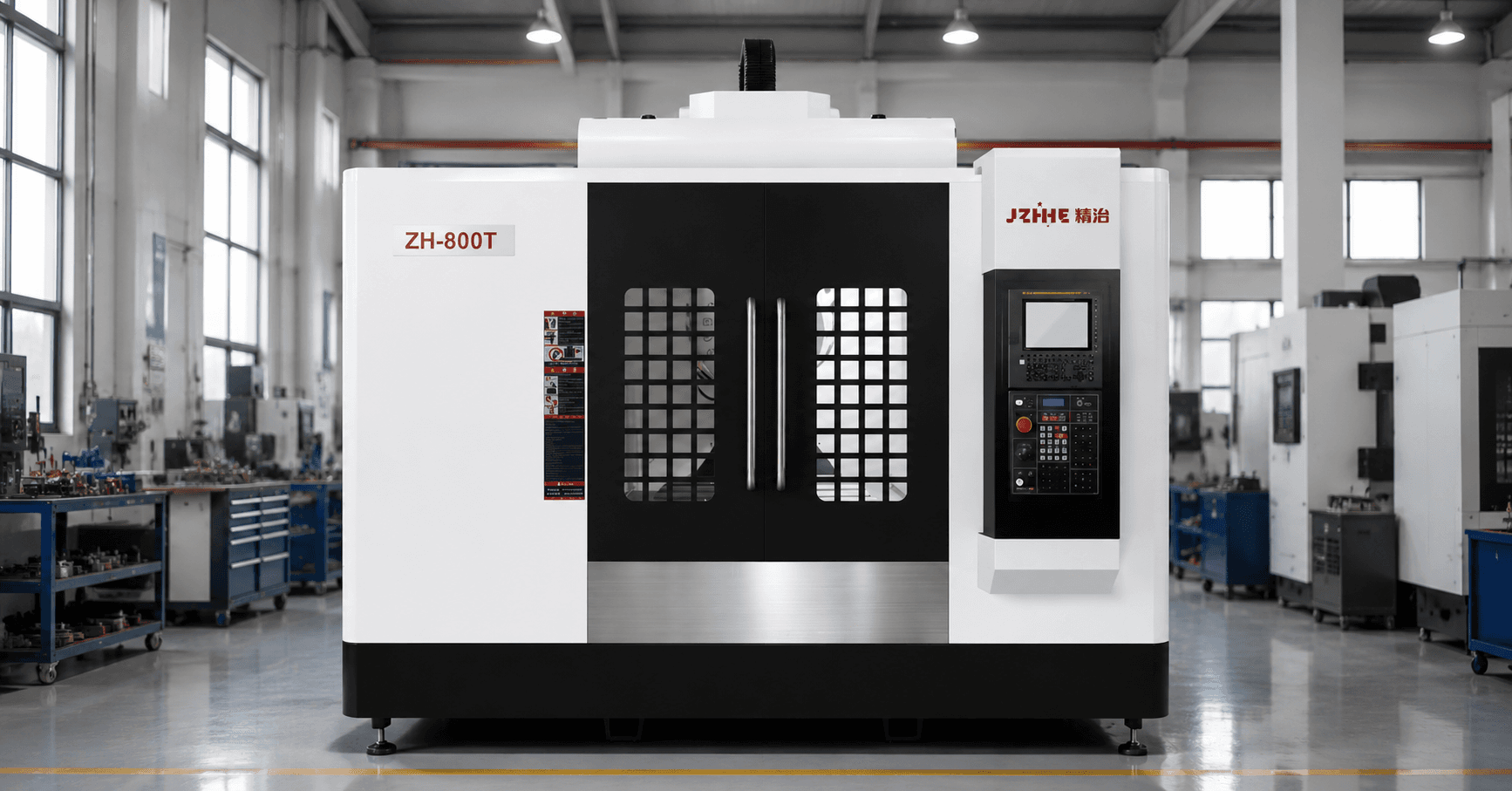
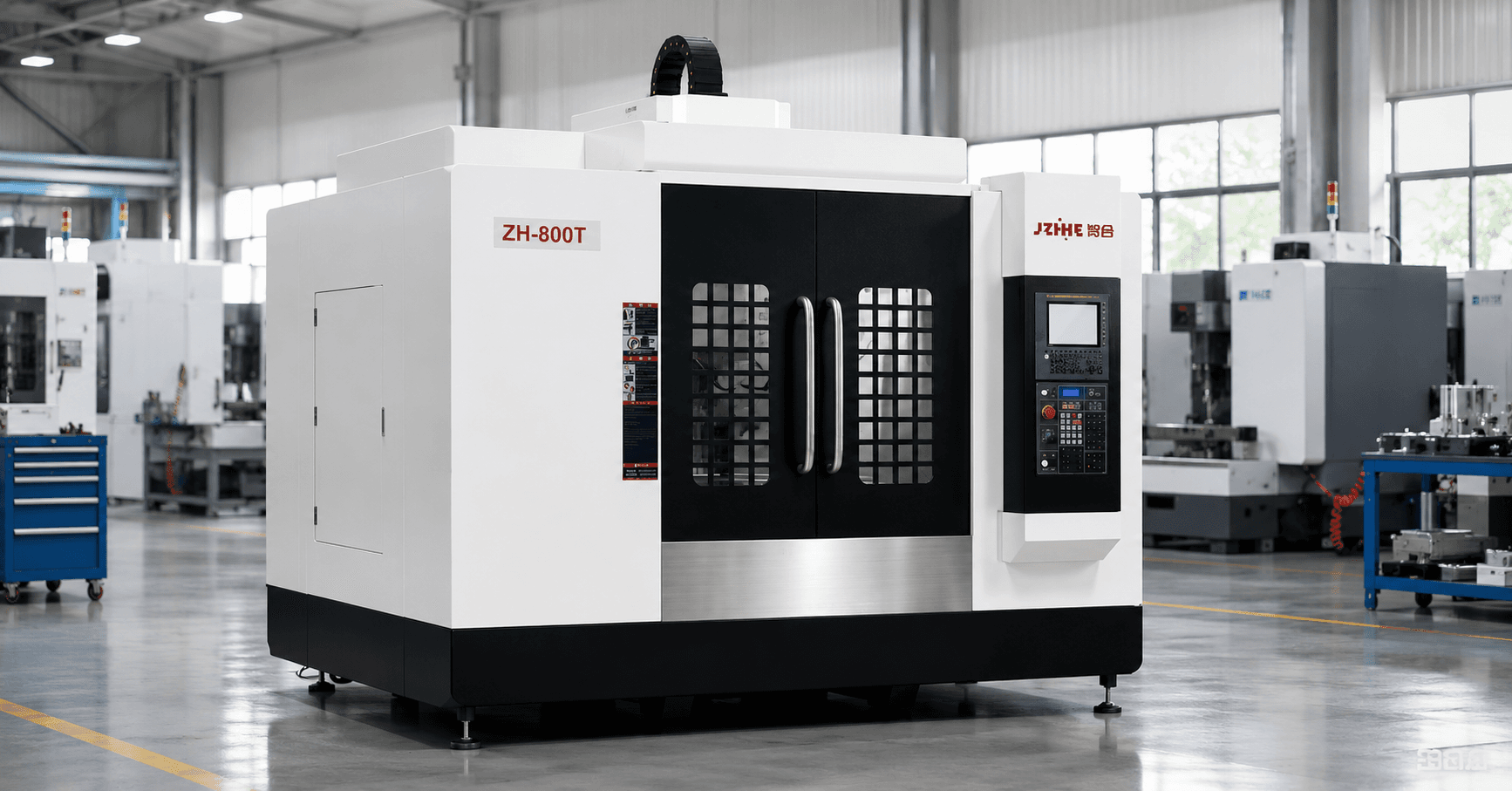
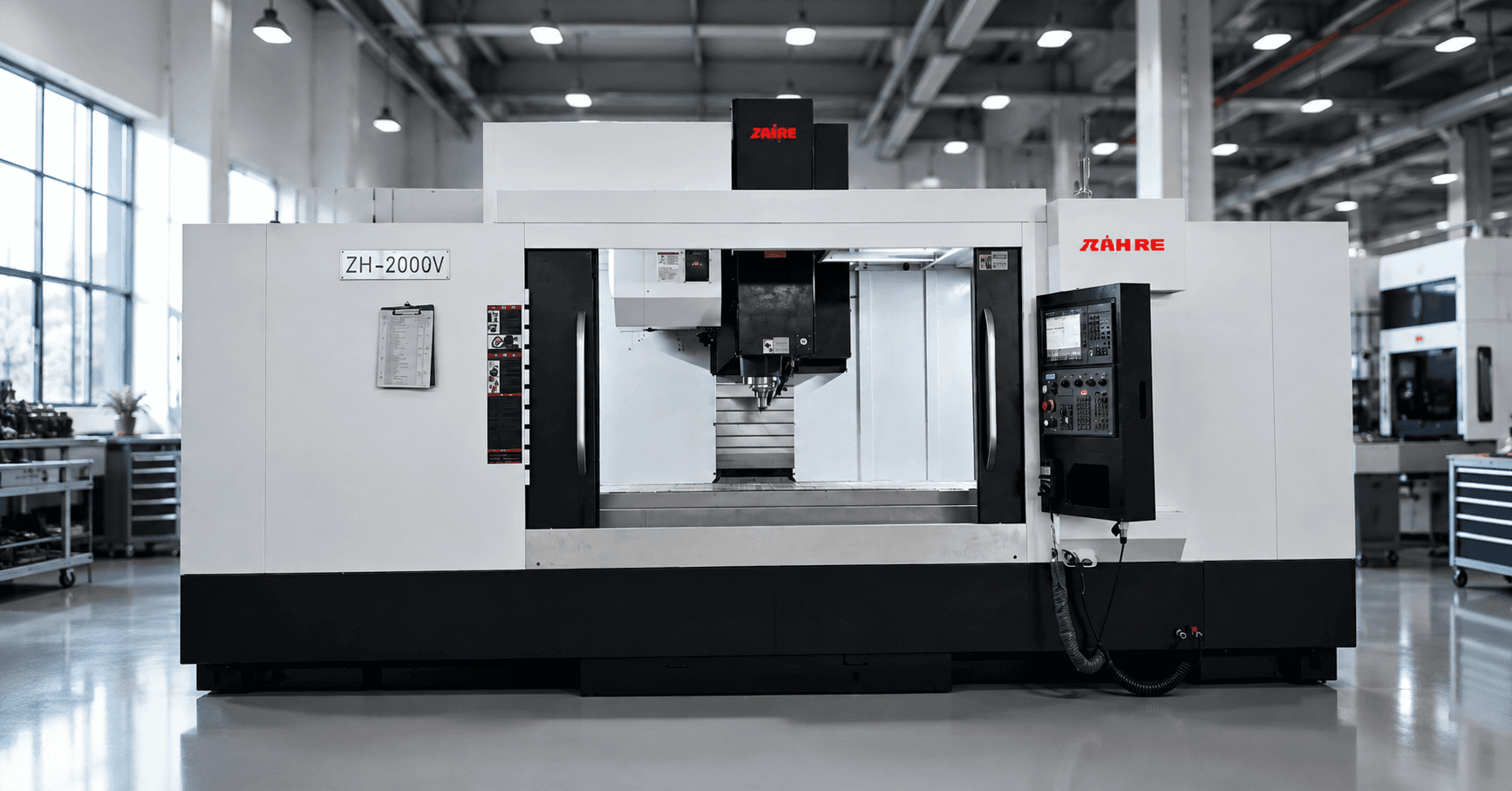
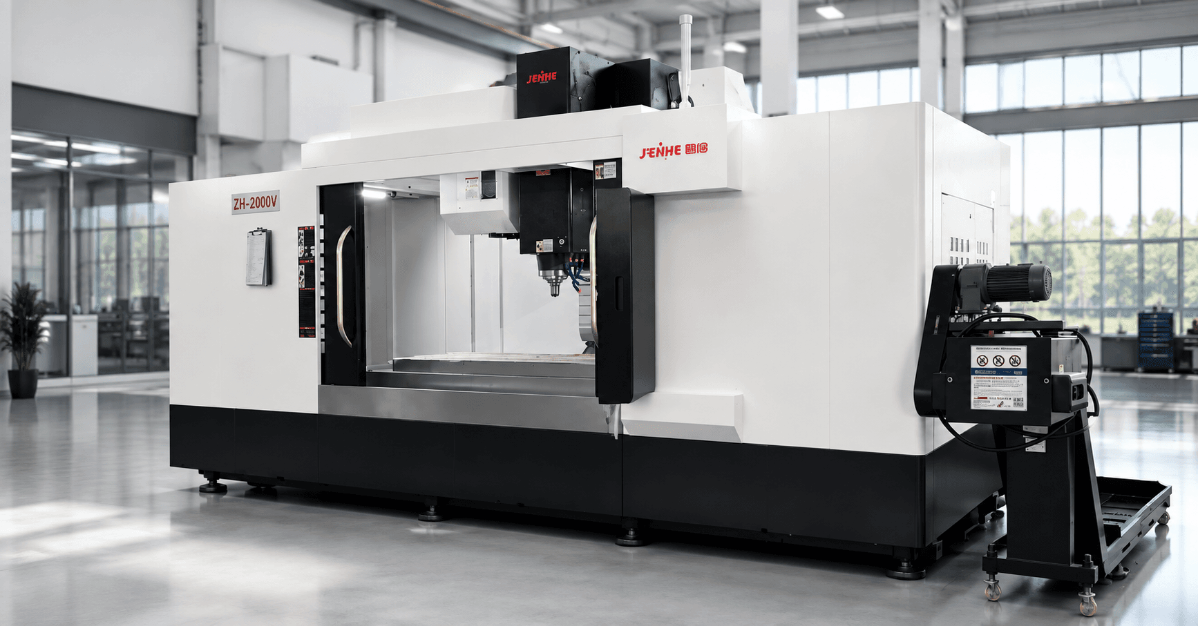
A high speed milling machining center should be evaluated with a motion-time waterfall that separates programmed feed from the time lost or gained in short segments, acceleration, deceleration, corner control, spindle ramp, tool changes, chips, inspection, and recovery. Maximum spindle speed and rapid rate do not predict the accepted-part cycle by themselves.
The waterfall follows time from the NC program to the released component. It reveals whether the bottleneck is cutting physics, controller processing, axis motion, toolpath design, machine dynamics, material handling, or downstream work.
Waterfall Layer 1: Count the NC Path Density
Measure program size, block count, average segment length, curve representation, tolerance settings, and the concentration of short moves. Fine surface toolpaths can contain many segments that prevent axes from reaching programmed feed.
Compare the same geometry using controlled CAM tolerances and output methods. Do not reduce path density so aggressively that form, finish, or collision clearance is compromised. Record postprocessor and controller versions because digital changes can alter motion.
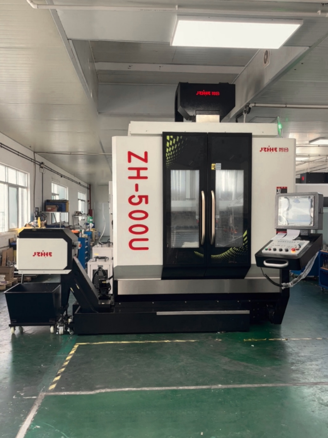
Waterfall Layer 2: Measure Look-Ahead and Smoothing
Look-ahead and smoothing influence how the control prepares for corners and rapid direction changes. Define the approved mode, path tolerance, contour priority, and surface target. More aggressive smoothing may improve motion but change the relationship between programmed and actual geometry.
Use representative corners, blends, and freeform surfaces. Inspect form as well as appearance. Keep controller settings traceable in the setup and program release.
Waterfall Layer 3: Map Acceleration and Corner Slowdown
Record actual feed through straight moves, small arcs, corners, reversals, and simultaneous axis changes. A high programmed feed can spend most of the cycle accelerating and decelerating. Identify the features causing the largest velocity loss.
Change toolpath direction, engagement, corner strategy, segment length, or local feed only through controlled trials. The objective is stable accepted output, not forcing maximum acceleration into a weak tool or flexible feature.
| Time layer | Measure | Possible action |
|---|---|---|
| NC processing | Block density and buffer behavior | Post, tolerance, curve output review |
| Axis motion | Actual versus programmed feed | Smoother path and fewer abrupt changes |
| Spindle | Ramp, orientation, load, warm-up | Sequence tools and speeds deliberately |
| Cutting | Engagement, chip load, wear | Optimize within the proven window |
| Noncutting | Tools, probing, chips, handling | Remove the largest stable loss first |
Waterfall Layer 4: Include Spindle Transitions
Measure spindle acceleration, deceleration, orientation, warm-up, and speed changes between tools. Frequent transitions can consume meaningful time in short-cycle work. Group operations where technically appropriate without sacrificing tool life, finish, or chip control.
Review balance, holder condition, tool projection, runout, and thermal behavior at the intended speed. A high speed milling machining center needs a complete toolholding and process system, not only a high nameplate speed.
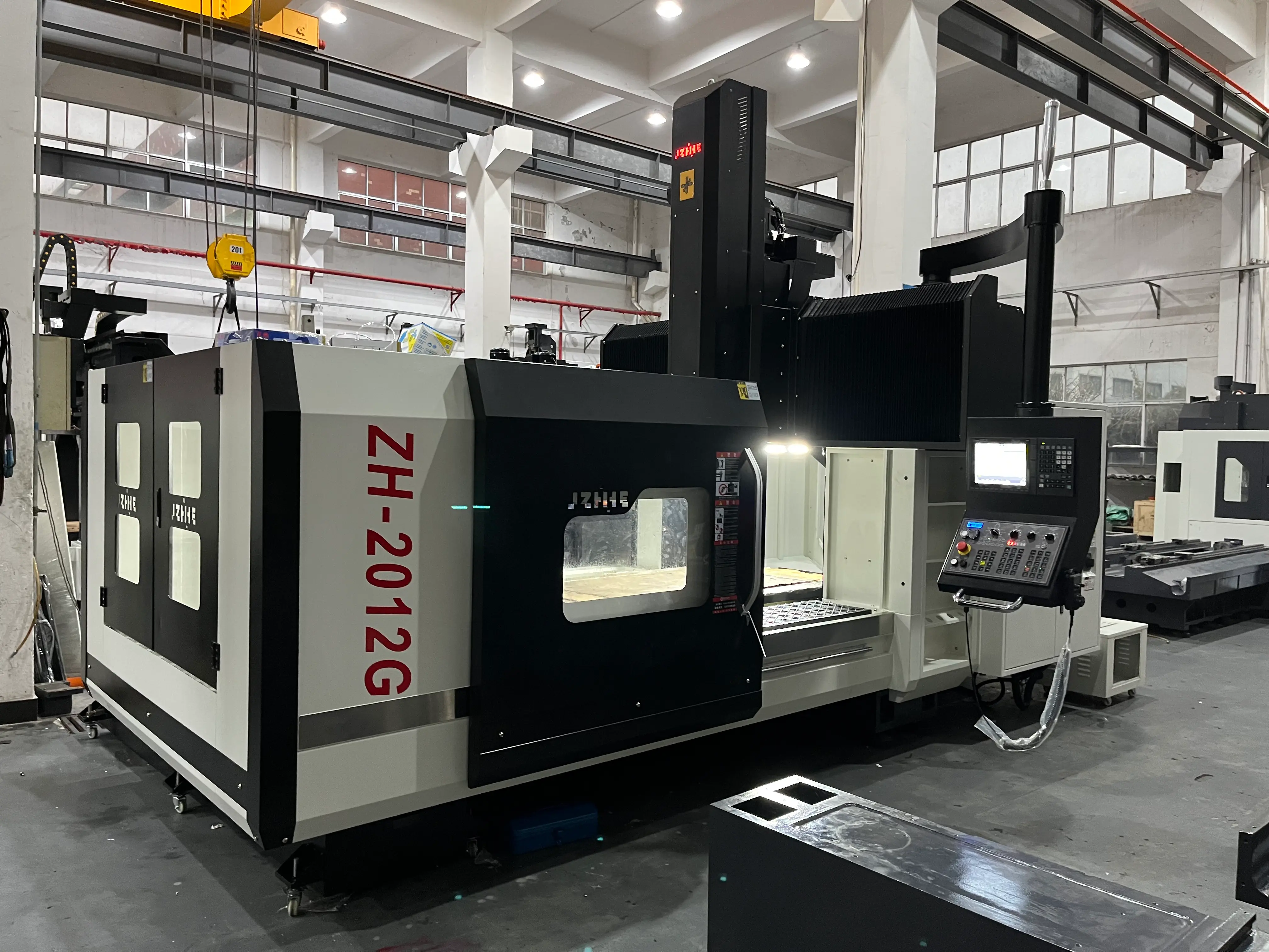
Waterfall Layer 5: Separate Cutting From Air Time
Break automatic time into cutting, rapid positioning, linking moves, retracts, tool changes, probing, spindle transitions, coolant commands, chip clearing, and programmed dwell. Focus on the largest repeatable elements.
A shorter retract or better linking path can save more than a small increase in cutting feed, especially on detailed parts. Verify every change through collision simulation and representative cutting.
Waterfall Layer 6: Add Tool-Life Cost
Track parts per tool or edge, replacement time, sister tools, presetting, offsets, failure mode, and the quality trend before replacement. A fast cycle that halves stable tool life may reduce availability and increase risk.
Define planned replacement and abnormal-event rules. Include the parts that require review after breakage, pullout, unexpected load, or finish deterioration.
Waterfall Layer 7: Count Chips, Inspection, and Recovery
Measure loading, unloading, fixture cleaning, chip evacuation, washing, deburring, inspection, program selection, alarms, and restart. Fine milling can create dust, small chips, delicate edges, and surfaces that require careful handling.
Review the milling machining center range and the high-speed milling product page as configuration references, then validate the actual program and part.
Run a Short-Segment Stress Test
- Select a representative program containing short segments, corners, blends, and longer cuts.
- Freeze CAM, post, controller mode, tools, material, fixture, and inspection.
- Record actual motion and time by waterfall layer.
- Inspect form, finish, burrs, tool wear, temperature, and offsets.
- Repeat across the expected production and tool-life window.
- Approve only changes that improve accepted output without moving risk downstream.
Set the Accepted-Part Speed Boundary
Define the highest stable condition for geometry, finish, tool life, chips, temperature, inspection, and operator work. This boundary may be below maximum machine settings. Keep a warning range and stop rule rather than treating every slowdown as lost productivity.
Where High Speed Does Not Pay
High-speed architecture is not automatically the best fit for heavy low-speed cutting, very long tools, unstable fixtures, abrasive contamination, small batches with large setup effort, or parts dominated by manual inspection and finishing. A slower nominal machine can deliver lower accepted-part cost when the complete route is more stable.
FAQ
Why does actual feed stay below programmed feed?
Short segments, corners, acceleration limits, smoothing, path tolerance, and simultaneous axis changes can prevent full feed.
Does more look-ahead always improve quality?
No. Controller modes and smoothing must be balanced against form accuracy, finish, and the approved toolpath.
Should tool-change time be included?
Yes. Include every automatic and attended element that affects accepted output over the representative batch.
What is the best stress-test program?
Use a real or representative program containing the path density, corners, blends, tool reach, and surface requirements that drive the decision.
Request a Motion-Time Review
To evaluate a high speed milling machining center, send the drawing, material, tool list, CAM and post information, representative NC program, segment density, current cycle breakdown, finish and form targets, tool-life data, chip and cleaning requirements, inspection time, and annual volume. Use the contact page to request a program and configuration review.