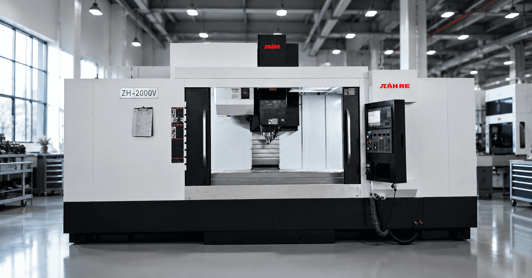
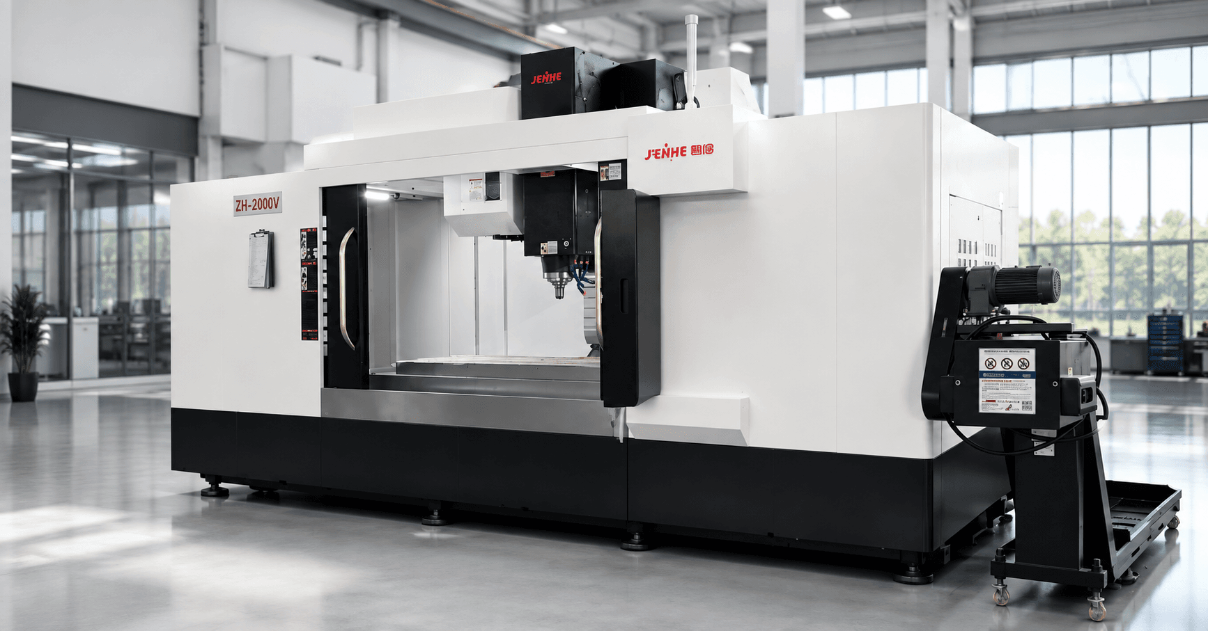
Box-type parts are usually difficult because several faces must agree with the same datums. A gearbox housing, hydraulic manifold, pump body, valve body, or machine base may require bores, mounting faces, threads, pockets, and hole patterns on multiple sides. Every additional setup introduces handling, cleaning, reclamping, datum transfer, and inspection work.
A suitable horizontal machining center for box parts can place several faces within one controlled setup, let chips fall away from the cutting zone, and support repeat production with rotary workholding or pallets. The investment makes sense when reduced setups, better feature relationships, and higher spindle utilization outweigh the added fixture, programming, and machine cost.
This guide explains how to evaluate the part family, work envelope, spindle, rotary axis, fixture, tooling, accuracy, and automation before choosing an HMC.
Horizontal Machining Center for Box Parts: Count Faces, Setups, and Annual Handling
An HMC is most valuable when the same fixture can present several important faces to the spindle without losing the datum. It is especially useful for repeat housings and prismatic parts with related bores or features on adjacent sides. A VMC may remain the simpler choice for low-volume work that is mainly accessed from above.
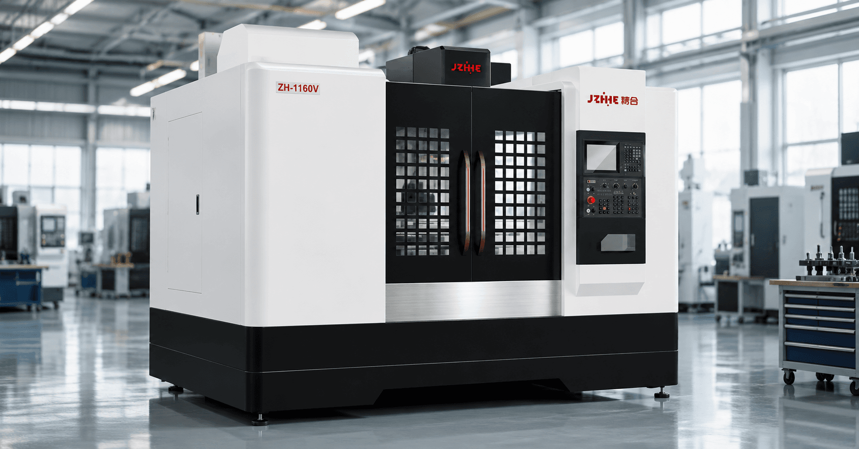
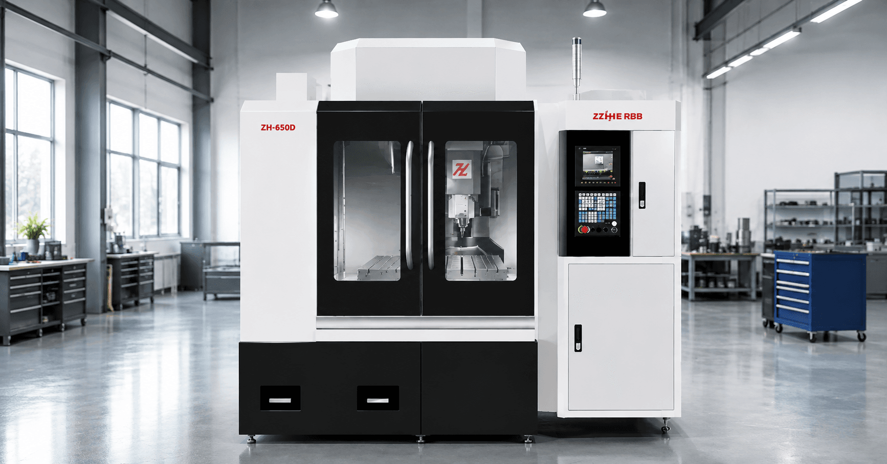
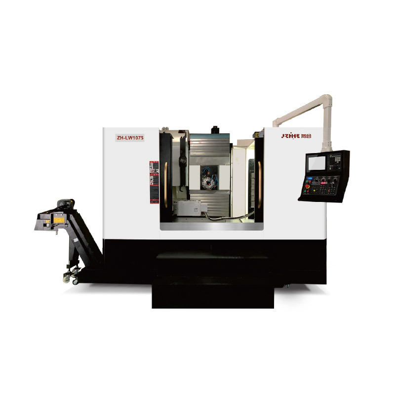
Zhihe CNC states that its horizontal machining center series is intended for box-type parts, automotive components, multi-face machining, and continuous production. The application should still be proven with the buyer's actual drawing and production target.
Why Box Parts Create Setup and Datum Risk
A box part often has a functional relationship between features on different faces. A bearing bore may need to align with another bore. A mounting face may control the location of ports and threaded holes. A cover face may need flatness and perpendicularity relative to a main datum.
When the process uses several separate fixtures, each transfer creates opportunities for error:
- Chips or burrs under a locating surface.
- Different clamping force and part distortion.
- Operator variation during loading and indicating.
- Accumulated datum-transfer error between faces.
- Extra work-in-process and queue time.
- Repeated inspection before the next operation.
An HMC does not remove every risk, but it can keep more features tied to one setup and one controlled rotary coordinate system.
Start With a Face and Feature Map
Mark every machined face on the drawing. For each face, list the roughing, finishing, drilling, tapping, boring, and probing operations. Identify the primary datum, secondary datum, critical feature relationships, longest tool, deepest bore, and surface that must remain accessible for clamping.
Then compare three process routes:
- Current process and number of setups.
- VMC process with fixtures or a fourth axis.
- HMC process with a rotary table, tombstone, or pallet arrangement.
The goal is not to force every operation into one cycle. The goal is to remove the transfers that create the highest cost or quality risk.
Check the Rotary Envelope, Not Only XYZ Travel
Horizontal work zones can be deceptive. A part may fit before rotation but collide with the spindle, enclosure, tool, neighboring fixture, or chip conveyor path after indexing.
Confirm pallet or table dimensions, center height, rotary swing, maximum load, fixture height, workpiece overhang, spindle-nose clearance, longest tool, and access for the loader or crane. Model the setup at every indexed angle used by the program.
The proposed HMC should also leave space for clamps, hydraulic lines, probing moves, and chip escape. A fixture that barely clears during a clean simulation may be difficult to operate safely in production.
Spindle Torque, Tool Reach, and Boring Stability
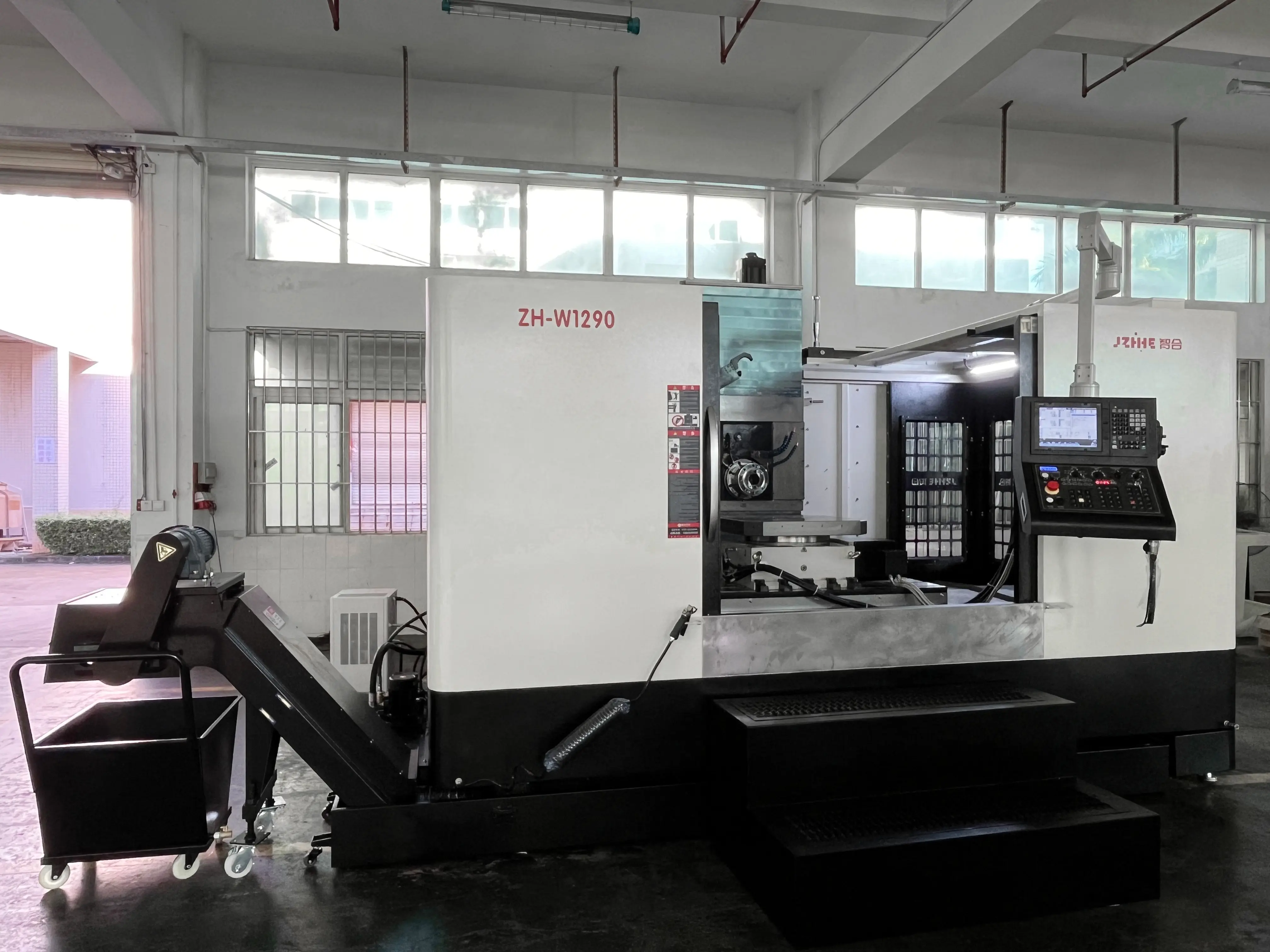
Box parts can combine face milling, pocket roughing, drilling, tapping, and long boring operations. The spindle needs usable power and torque in the planned speed range, not merely a high maximum rpm.
Long bores and deep features make tool overhang important. Review holder interface, tool diameter, boring-bar length, spindle condition, coolant delivery, and fixture support. A machine with adequate travel can still produce poor bores if the tool is too flexible or the setup allows vibration.
Ask the supplier to identify the most demanding cut and the longest tool. Request estimated spindle load and the recommended roughing and finishing sequence. These answers reveal whether the proposed spindle is matched to the part or selected from a generic catalog table.
Fixture Design Determines Whether One Setup Is Really Better
The fixture must locate the part repeatably, resist cutting loads, avoid distortion, provide tool access, and allow chips to leave. A tombstone can hold several parts or several fixtures, but loading density should not block tools or create chip traps.
For cast housings, consider variation in raw locating surfaces and machining allowance. For thin-wall parts, control clamping force and support. For hydraulic components, protect ports and sealing surfaces from chips and damage.
Hydraulic or pneumatic clamping may reduce manual time, but it needs pressure monitoring, safe line routing, and a recovery plan. Manual fixtures can be appropriate for lower volume when they are simple, repeatable, and easy to clean.
Chip Evacuation Is a Major HMC Advantage Only When Planned
Gravity can help chips fall away from vertical faces, but chips can still collect inside cavities, on tombstones, around clamps, and under locating points. Coolant nozzles, through-spindle coolant, washdown, filtration, conveyor capacity, and fixture drainage must support the actual chip volume.
Run the trial long enough to expose accumulation. A clean ten-minute demonstration does not prove an unattended shift. Check whether chips affect probing, part seating, tool life, surface finish, or rotary movement.
Tool Magazine and Sister Tools Support Continuous Production
Multi-face parts often require many tools. Build the complete list, including roughers, finishers, spot drills, drills, taps, boring tools, chamfer tools, probes, and backup tools. Add sister tools for operations likely to reach the tool-life limit during a pallet cycle.
Review maximum tool diameter and length, heavy-tool positions, change time, tool-life management, broken-tool detection, and how an operator replaces a worn tool without disrupting the process. Magazine capacity should support the planned family of parts, not only the first sample.
Bore Relationships and Rotary Accuracy Need Process Evidence
An HMC can reduce datum transfers, but the rotary axis, fixture, spindle, thermal condition, tool, and program still influence the result. Identify the bores and faces that must relate across indexed positions.
Agree on machine checks and a representative trial part. Measure the features after the part is unclamped and stabilized. Record the fixture, work offsets, rotary positions, warm-up, tools, inspection equipment, and measurement method.
| Decision factor | What to verify | Why it matters |
|---|---|---|
| Part family | Faces, features, setup count, annual volume | Shows whether multi-face access creates value |
| Envelope | Rotary swing, load, fixture, tool, clearance | Prevents collision and unusable work space |
| Cutting | Torque, tool reach, boring stability, coolant | Protects cycle time, bore quality, and tool life |
| Production | Magazine, pallets, chip handling, probing | Supports repeat or unattended operation |
| Acceptance | Rotary tests, trial part, feature relationships | Connects machine capability to the drawing |
When a VMC May Be the Better Choice
A VMC can be more economical when parts are low volume, top-side features dominate, fixtures are simple, operators are available, and setup transfer does not threaten critical relationships. It may also be easier to program and maintain in a shop built around vertical machines.
Do not compare only machine purchase price. Estimate annual loading time, setup labor, queue time, fixture count, inspection, scrap risk, spindle utilization, and floor space. The correct answer depends on cost per acceptable part and the flexibility required by the business.
Buyer Checklist Before Ordering
- Representative drawings and annual quantities for the part family.
- Face map and current setup route.
- Raw and finished weights, fixture concept, and clamping method.
- Critical bore, datum, flatness, and positional requirements.
- Longest and heaviest tools, spindle demand, and coolant needs.
- Rotary envelope and collision simulation at all indexed angles.
- Magazine capacity, sister tools, pallets, probing, and automation.
- Trial-part plan, inspection method, training, and support scope.
FAQ
Are all box parts good candidates for an HMC?
No. The strongest candidates need several faces, have meaningful datum relationships, repeat in sufficient volume, or consume excessive handling on the current process.
How many setups can an HMC remove?
It depends on tool access, clamping surfaces, feature locations, and inspection needs. Map the actual route rather than assuming every face belongs in one cycle.
Does an HMC guarantee better accuracy?
It can reduce datum-transfer error, but accuracy still depends on the rotary axis, fixture, spindle, tools, thermal condition, program, and measurement process.
What information is needed for a machine recommendation?
Send drawings, material, raw size, weight, critical tolerances, annual volume, current setup route, target cycle, controller preference, and destination factory information.
Should the trial use the buyer's real casting?
Yes when possible. Real stock exposes variation, hard spots, allowance, chip behavior, clamping, and tool-life issues that a simple test block may hide.
Ask Zhihe CNC to Review the Part Family
To evaluate a horizontal machining center for box parts, send Zhihe CNC two or three representative drawings, annual quantities, current setup times, critical bore relationships, and factory constraints. The engineering inquiry form can be used to request a machine recommendation, fixture discussion, trial plan, and quotation.