The Mold Defect Atlas: Start With the Failure Pattern
| Atlas zone | Typical concern | Control record |
|---|---|---|
| Parting or shutoff | Mismatch, witness or edge damage | Datum and marked inspection |
| Rib and slot | Tool reach, chips and corner condition | Tool and path sheet |
| Texture zone | Tool marks and polishing allowance | Surface boundary |
| Hole and insert | Position, depth and fit | Gauge and raw data |
| Handoff | Protection, polishing and revision | Transfer passport |
Read the Mold Component Before Choosing the Machine
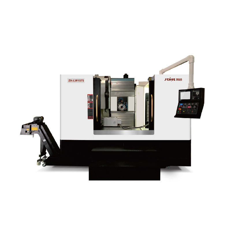
Zhihe CNC turns witness lines, corners, thin ribs, texture zones, tool marks and polishing boundaries into a mold-component defect atlas. A vertical machining center for plastic mold components decision should connect the declared part family to setup, tools, support work, inspection, recovery and a stated commercial boundary. The strongest evidence is reproducible by the receiving team and transparent about what has not been tested.
Atlas Zone A: Material, Datum and Access Defects
Mark the Mold Function Zones
Divide the component into parting, shutoff, cavity, core, rib, slot, insert, ejector, cooling, texture and nonfunctional zones. State the drawing requirement and downstream process for each.
A vertical machining center for plastic mold components should be judged on the zones that control mold fit and molded-part appearance. Zhihe CNC uses a marked atlas to keep a general surface claim from hiding local risks.
Freeze Material and Heat-Treatment State
Record steel grade, hardness or declared condition, stock allowance, heat treatment stage and stress-relief assumptions. Tool behavior and finishing allowance depend on the actual state entering the machine.
Keep the material and process route with the program revision. If heat treatment or stock changes, reopen affected tool-life, geometry and finish evidence.
Design the Datum Around Mold Assembly
Define assembly references, supports, clamps, probe points, work offsets and reload strategy. Avoid locating on a surface that will later be polished or changed without a controlled transfer.
Trial unload and reload. Inspect related insert, shutoff or hole features. Separate fixture repeatability from cutting or measurement variation.
Plan Deep Ribs and Narrow Slots
List tool diameter, flute length, holder, projection, reach, engagement, coolant or air, chip evacuation and corner requirement. The longest or smallest tool may control the real route.
Use simulation as model evidence and a controlled prove-out as physical evidence. Preserve the approved assembly and collision assumptions.
Atlas Zone B: Tool, Surface and Feature Defects
Set the Polishing Boundary
State which surfaces are machine-finished, which receive polishing, the allowed stock, the owner and the acceptance after polishing. Do not use undocumented polishing to hide a machining defect.
A vertical machining center for plastic mold components creates value when the machining and polishing teams share the same boundary and revision. Keep marked zones and measurements before handoff.
Control Witness Lines and Blends
Define blend areas, step-over, tool path direction, tool state, offsets and inspection method. Compare early and late pieces or surfaces around a planned tool event.
When a line appears, check datum, program, tool wear, runout, holder, clamping and measurement before changing multiple variables.
Protect Texture and Cosmetic Zones
Mark areas that will carry texture or form a visible molded surface. Define allowable tool marks, cleaning, protection and downstream handling. Avoid unsupported claims about the final molded appearance.
Use lighting, reference or numeric method as agreed. Preserve photos as context and raw measurements as release evidence.
Atlas Zone C: Handoff, Output and Release Defects
Build the Insert and Hole Route
Record hole, thread, counterbore, insert pocket, ejector and cooling features separately. State datum, size, position, depth, burr, gauge and sampling.
Keep drilling, tapping and pocket evidence traceable by feature identity. A correct cavity surface does not prove an insert fit or cooling connection.
Run the Defect Review Meeting
Review each atlas zone with applications, mold engineering, quality, polishing and production. Label defects as machining, material, handling, polishing or measurement issues with evidence.
Assign containment, correction, retest and owner. Keep accepted limitations visible to the buyer before commercial release.
Transfer the Mold Passport
Handoff drawing, atlas, material, fixture, tools, program, offsets, inspection, polishing boundary, protection, backups and open issues.
Reopen affected evidence after changes to mold revision, material, heat treatment, fixture, tool, program, gauge or polishing.
Create a Zone-by-Zone Trial Plan
Select one surface, rib, shutoff, insert pocket, hole family and transition that represents the mold’s real risk. Define tool, path, fixture, inspection and polishing boundary for each zone. Do not allow an easy cavity surface to stand in for the full component.
Use the same marked atlas during trial, inspection and handoff. The vertical machining center for plastic mold components decision becomes clearer when every reviewer sees the same zones and release question.
Review Tool Capacity Against the Mold Mix
List tools by zone, holder, projection, preset, sister-tool need, life trigger and storage. Include the longest, smallest and finish-critical tools. A large magazine helps only when the approved mix and replacement route can use it.
Record unavailable or shared tools that create a queue. Connect tool capacity to the weekly mold-component mix rather than one prepared program.
Rehearse the Polishing Handoff
Transfer one accepted component with its atlas, measurements, protected surfaces and declared polishing allowance. Ask the polishing team to identify any ambiguity before work begins. Record any manual correction and the feature it affects.
After polishing, compare the interface zones and keep machining evidence separate from downstream work. This protects the original trial while showing whether the handoff package was usable.
Write a Mold-Component Release Note
Summarize material state, fixture, tools, protected zones, machining finish, polishing boundary, insert and hole results, accepted output and open issues. Link each conclusion to a drawing revision or test record.
Name the first change that reopens the atlas and the authority that approves it. Preserve superseded files so a returning mold revision can start from evidence rather than memory.
Plastic Mold Component Buyer FAQ: vertical machining center for plastic mold components
What is a mold defect atlas?
A marked map of functional zones, expected risks, inspection methods and process ownership.
Why separate polishing from machining?
Polishing has its own allowance, method and acceptance and should not hide machining defects.
What controls deep rib machining?
Tool diameter, projection, holder, reach, chips, corner requirement and controlled prove-out.
Why record heat-treatment state?
Hardness and process stage affect tool behavior, geometry, finish and allowance.
How should witness lines be investigated?
Check datum, program, tool wear, runout, holder, clamping and measurement.
How does Zhihe CNC review cosmetic zones?
Zhihe CNC uses marked zones and an agreed visual or numeric method without unsupported claims.
What belongs in an insert route?
Pocket, hole, thread, counterbore, datum, size, depth, burr, gauge and sampling.
When should the atlas reopen?
After changes to revision, material, heat treatment, fixture, tools, program or polishing.
Can one mold sample prove molded-part quality?
No. Molding conditions and downstream performance require separate evidence.
What should buyers send?
Send mold CAD, steel, hardness, zones, ribs, finish, polishing plan and inspection method.
Defect-to-Evidence Index
| Lane | Minimum record | Reopen when |
|---|---|---|
| Part | Representative and boundary features | Drawing, material or mix changes |
| Setup | Fixture, datum, tools, offsets and program | Fixture, holder or software changes |
| Quality | Gauge, sampling, raw data and disposition | Gauge or acceptance rule changes |
| Output | Complete time and released quantity | Labor, batch or support assumptions change |
Keep the Final Approval Traceable
Before commercial release, ask purchasing, engineering, production, quality and maintenance to confirm their evidence location and remaining concern. Record the final reviewer, approval authority, effective revision and next review date. This short approval record keeps the technical route usable after the original sourcing meeting ends.
If a later change affects only one feature, interface or support assumption, repeat the smallest sufficient evidence and preserve the unaffected results. Do not overwrite the original file. A proportional change route reduces unnecessary retesting while protecting the conditions behind the accepted machine and process decision.
Implementation Review
Convert the accepted vertical machining center for plastic mold components route into a short first-shift checklist. Confirm drawing revision, material or stock, setup identity, tools, program, gauge, cleaning or chip route, hold authority and escalation contact. Keep the checklist at the machine and in the shared quality file so a trained operator can follow the release logic without reconstructing the trial from scattered messages.
After the first representative lot, compare actual setup, support work, tool events, inspection queue, held quantity, rework and released output with the accepted route. Preserve the original record and mark each difference with evidence, owner and date. This keeps a practical improvement from becoming an undocumented capability claim and gives Zhihe CNC a focused basis for follow-up.
Carry the Evidence Into the Purchase Order
Attach the offered configuration, representative and boundary part conditions, fixture assumptions, critical tool assemblies, inspection route, accepted-time definition, training, spares, service contacts and exclusions. Tie payment or acceptance milestones to named evidence instead of calendar dates alone. For the vertical machining center for plastic mold components decision, keep every unresolved interface visible as a blocker, accepted limitation or dated deliverable with an approval owner.
Schedule a review after installation, the first accepted part, a normal tool-life event and the first representative production window. Compare the delivered setup, access, chips or cleaning, gauges, maintenance, held work and released output with the purchase file. Close each difference with repeated evidence, an accepted operating limitation or a dated action. Preserve the previous revision so later improvements remain traceable and no team silently changes the commercial boundary.
Bring the Decision to Zhihe CNC
Send Zhihe CNC controlled drawings or CAD, material and stock, critical features, annual volume, batch mix, fixture ideas, tool constraints, inspection methods, site conditions and service region. Review the Zhihe CNC product portfolio, the company and factory profile, and the engineering inquiry route. For vertical machining center for plastic mold components, request a dated configuration, representative trial, acceptance boundary, open-assumption list and named support owner.
Reference Boundary
The ISO machining-centre reference and the OSHA machine-guarding guidance provide testing or safeguarding context. They do not replace drawing-specific acceptance, local risk assessment, product certification, regulatory release or the buyer's operating procedures.