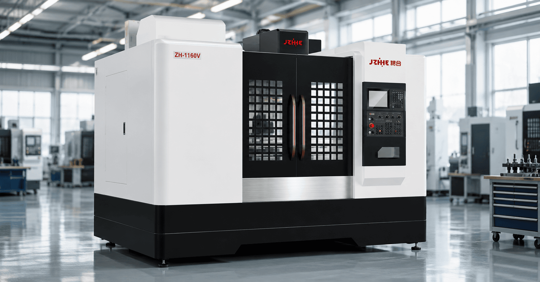
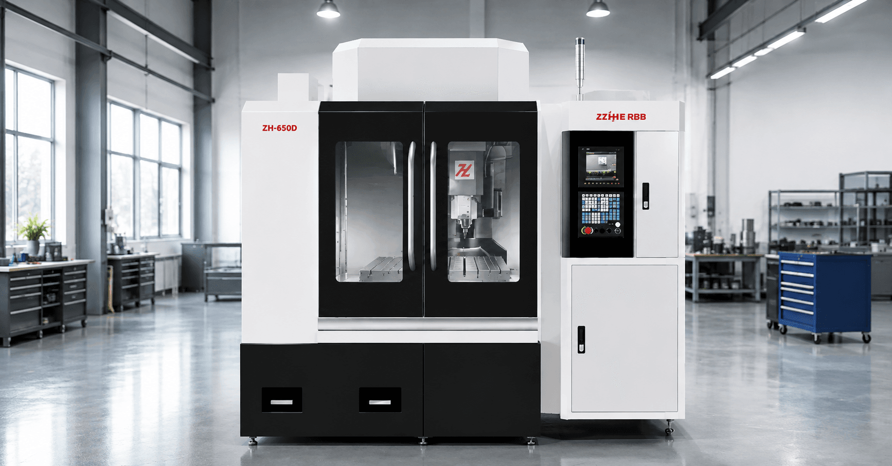
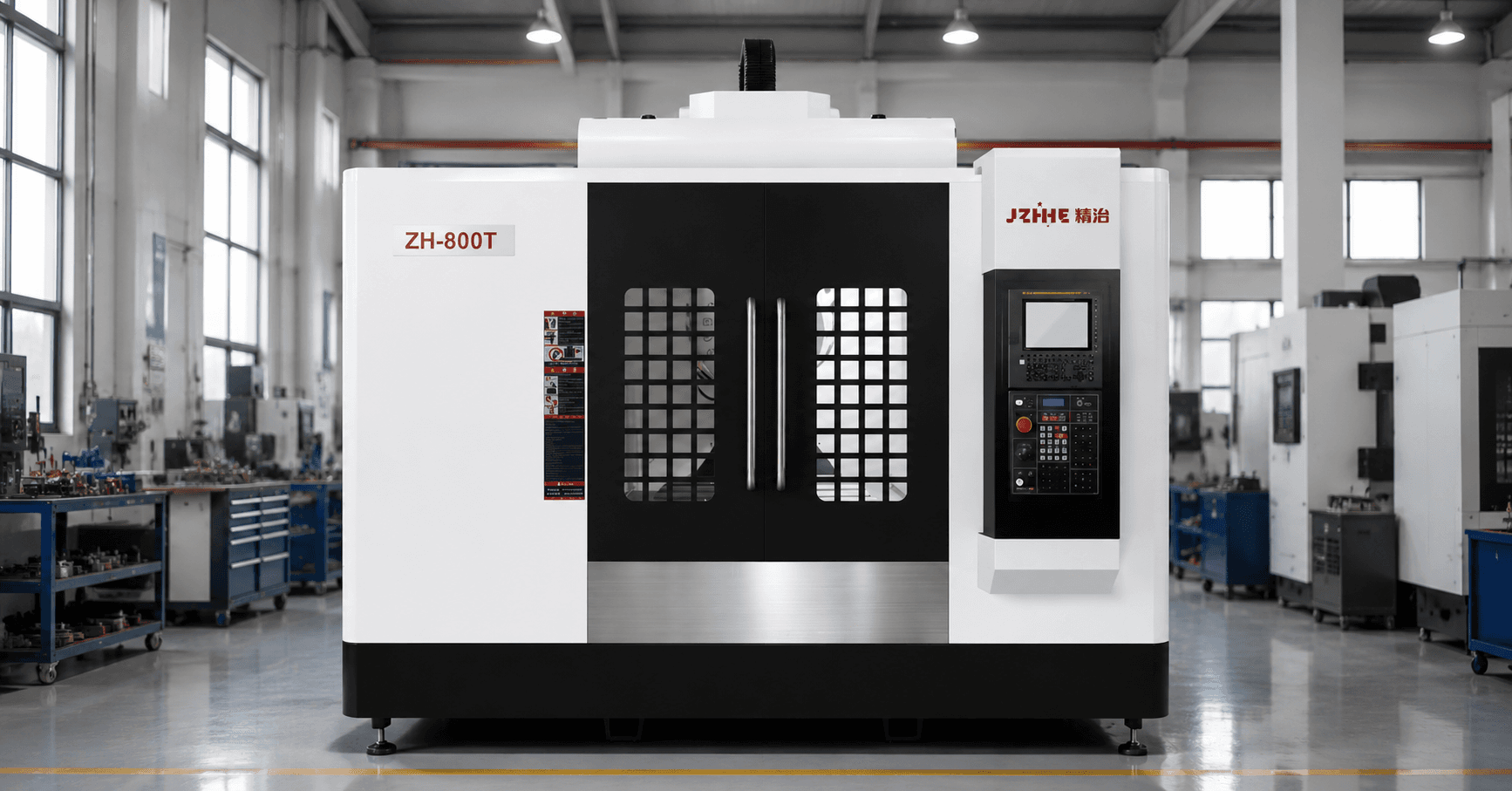
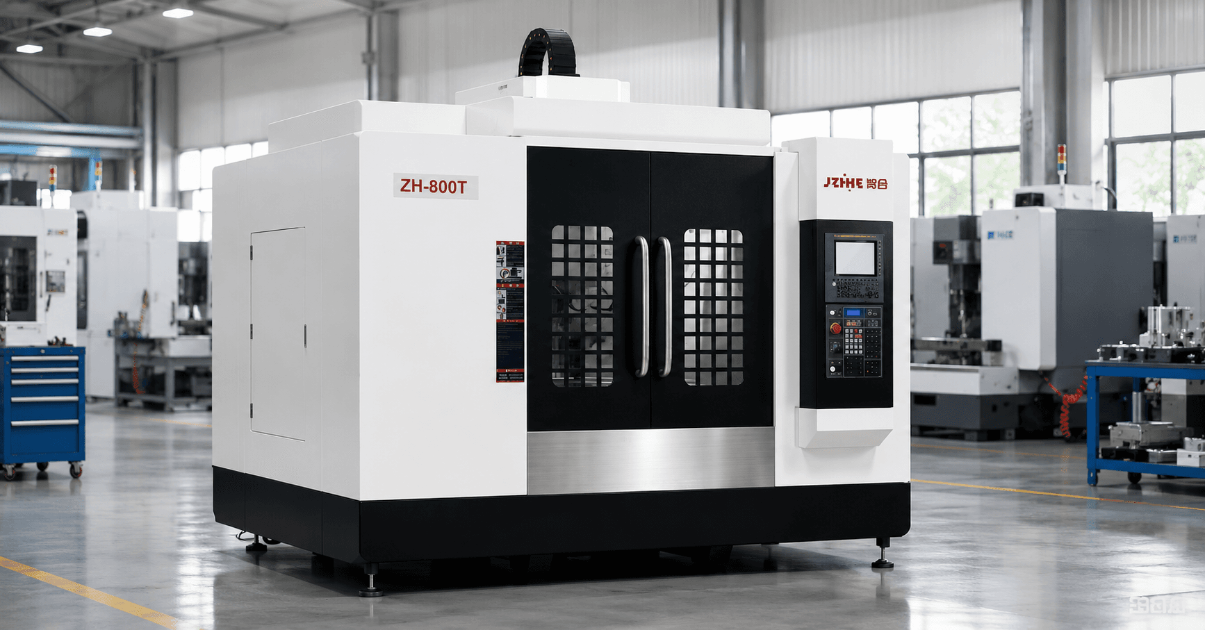
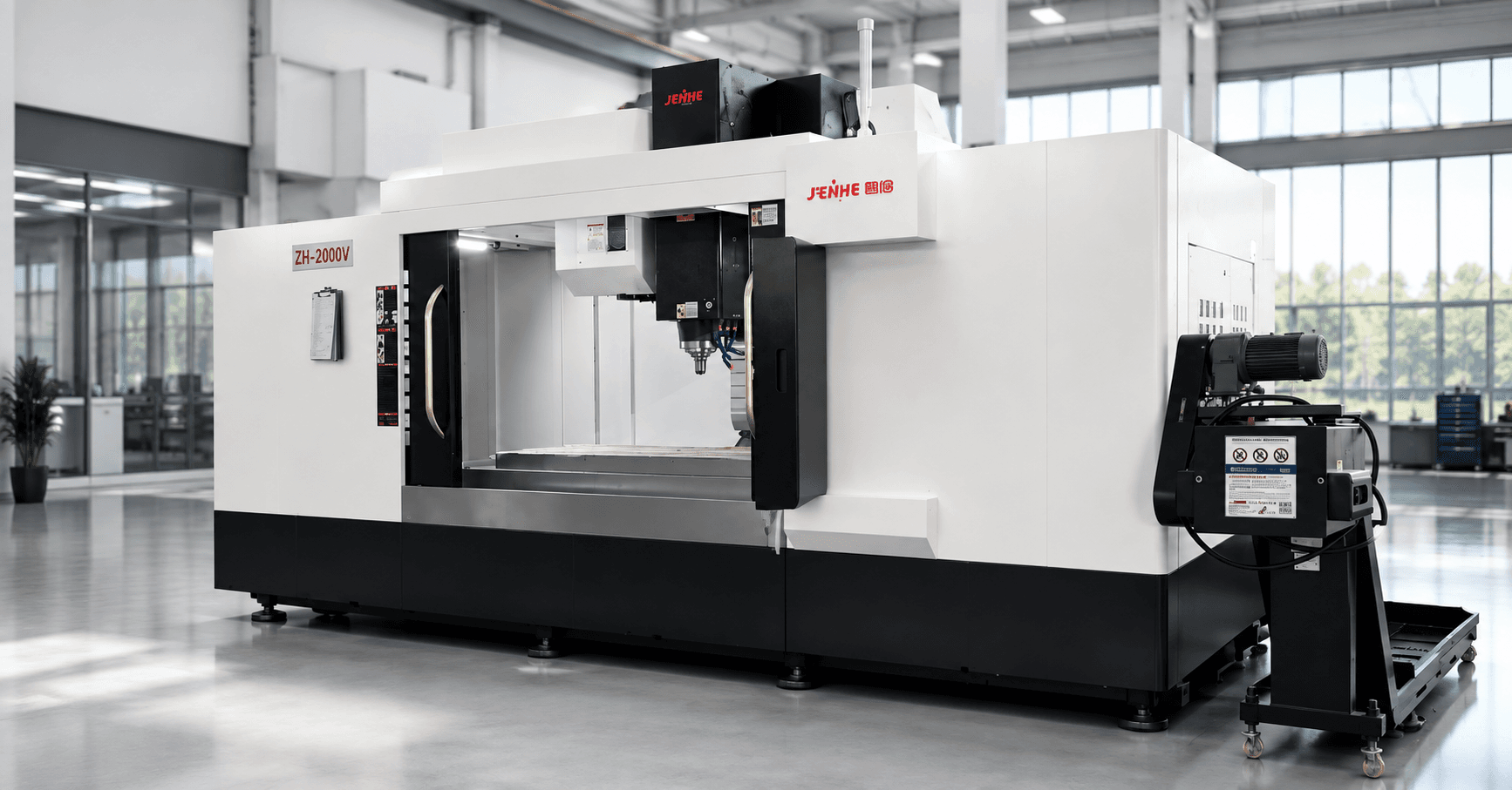
A VMC 850 machining center should enter production through a controlled 30-day launch, not move directly from delivery to an undefined output target. The useful sequence is to freeze the application baseline, verify machine health, prove one representative process, stabilize shift handoffs, challenge the operating window, and release standard work only after the evidence is complete.
The 850 label is not a universal specification. Travel, table capacity, spindle, tool magazine, controller, accuracy, coolant, probing, and options vary by configuration. Use this launch plan with the approved technical agreement and the actual part family rather than assuming that every machine carrying the same model class behaves identically.
Day 0: Freeze the Launch Baseline
Before installation activity begins, create a one-page baseline. Record the accepted configuration, utilities, foundation requirements, controller and software versions, toolholding standard, coolant type, probing package, chip system, safety scope, and responsible people. Add the representative drawing, blank condition, fixture revision, tool list, inspection method, cycle target, and expected shift pattern.
This baseline prevents the launch team from solving a moving target. If the fixture, drawing, material, or option list changes, record the change, owner, technical impact, and date. Do not let a new requirement quietly become evidence that the original machine failed.
Days 1-3: Establish Machine Health
Confirm utilities, leveling, lubrication, coolant circulation, spindle warm-up, tool-change behavior, axis movement, guarding, alarms, and chip removal. Review geometry and positioning records that apply to the configuration. Run the approved warm-up cycle and record temperatures, abnormal sound, vibration observations, and alarms rather than relying on memory.
Use a controlled reference artifact or simple test cut before loading the most difficult production part. The purpose is to separate machine-health questions from programming, workholding, tool, material, and inspection variables. Close installation issues with named actions and evidence.
Days 4-7: Prove the First Process
Select a representative part that exposes the main risks: longest tool, tightest positional relationship, most demanding finish, deepest pocket, largest chip volume, or most sensitive clamping condition. Prove datum strategy, fixture access, tool clearance, probing, offsets, cutting data, chip flow, and the inspection route. Record every manual intervention.
| Proof item | Evidence to capture | Release question |
|---|---|---|
| Datum and fixture | Setup photo, revision, clamp sequence | Can another operator reproduce it? |
| Tooling | Holder, gauge length, life rule, spare | Is the tool window defined? |
| Program | Approved revision and backup | Can the released file be identified? |
| Quality | First-off report and measurement method | Are results traceable to conditions? |
| Cycle | Automatic, attended, and recovery time | Is output based on accepted parts? |
Week 2: Stabilize Shift Handoffs
A successful first-off part is not yet a stable process. Run the VMC 850 machining center across the intended shifts and operators. Standardize startup, warm-up, tool loading, offset approval, coolant checks, fixture cleaning, first-piece inspection, in-process checks, program selection, and shutdown. A handoff should state machine status, tool life, open quality issues, remaining material, and any abnormal event.
Measure first-piece acceptance by shift. If one operator consistently recovers the process through experience, convert that knowledge into a setup sheet or remove the source of variation. Training is complete only when the process is repeatable without the original engineer standing beside the machine.

Week 3: Challenge the Operating Window
Test the normal range of material lots, tool age, ambient conditions, operators, and batch lengths. Do not deliberately abuse the process; vary the conditions that production will genuinely see. Track spindle load, tool wear, burr growth, dimensional drift, coolant condition, chip accumulation, stoppages, and inspection results.
Define green, warning, and stop limits. For example, a tool-life rule should state the monitored signal, review point, replacement point, and owner. A dimensional trend should trigger a controlled response before a nonconforming part appears. This is more useful than a single best cycle achieved during demonstration.
Week 4: Release Standard Work
Release only the documents that match the proven condition: drawing, program, fixture, tool list, setup instructions, inspection plan, maintenance checks, spare list, backup, and training record. Store revision-controlled copies where operators and engineers can retrieve them. Archive obsolete files so they cannot be selected by mistake.
Review the vertical machining center range for the current platform context, but keep model approval tied to the quoted configuration. The launch pack should also list unresolved improvements separately from mandatory acceptance items.
A Scorecard for Daily Readiness
- Utilities, lubrication, coolant, warm-up, and safety checks complete.
- Correct program, fixture, drawing, and tool revisions verified.
- First-piece result accepted with the approved measurement method.
- Tool-life status and replacement rules visible to the next shift.
- Chip, cleaning, and preventive-maintenance tasks within limits.
- Open alarms, deviations, and quality holds have named owners.
Where an 850-Class VMC Does Not Fit
This machine class is not automatically the best choice when the mounted envelope exceeds travel or table limits, long tools create access or rigidity problems, multi-face work requires repeated datum recovery, heavy cutting exceeds the stable spindle-duty window, or part volume cannot justify the fixture and process-development effort. A different vertical, horizontal, gantry, drilling-tapping, or five-axis architecture may lower total risk.
FAQ
Does the 850 designation guarantee a specific travel?
No. Naming varies. Confirm the current specification, options, table, load, spindle, tool system, and clearances in the technical agreement.
When should the cycle target be approved?
Approve it after the quality method, tool-life rule, operator work, chip handling, and normal production conditions are included.
How many parts should a launch trial run?
Use enough parts and time to expose warm-up, tool wear, shift, material, and cleaning effects. The correct quantity depends on the risk and batch pattern.
What belongs in the final release pack?
Include approved revisions, acceptance results, programs, backups, setup sheets, inspection plans, maintenance tasks, training records, and open-action ownership.
Request a 30-Day Launch Review
To plan a VMC 850 machining center launch, send the representative drawing, blank, material, fixture concept, critical dimensions, tool list, cycle target, shift pattern, utilities, destination, and required start-of-production date. Use the contact page to request a configuration review and launch checklist, and compare the wider machining center portfolio if the application sits near the limits of an 850-class platform.