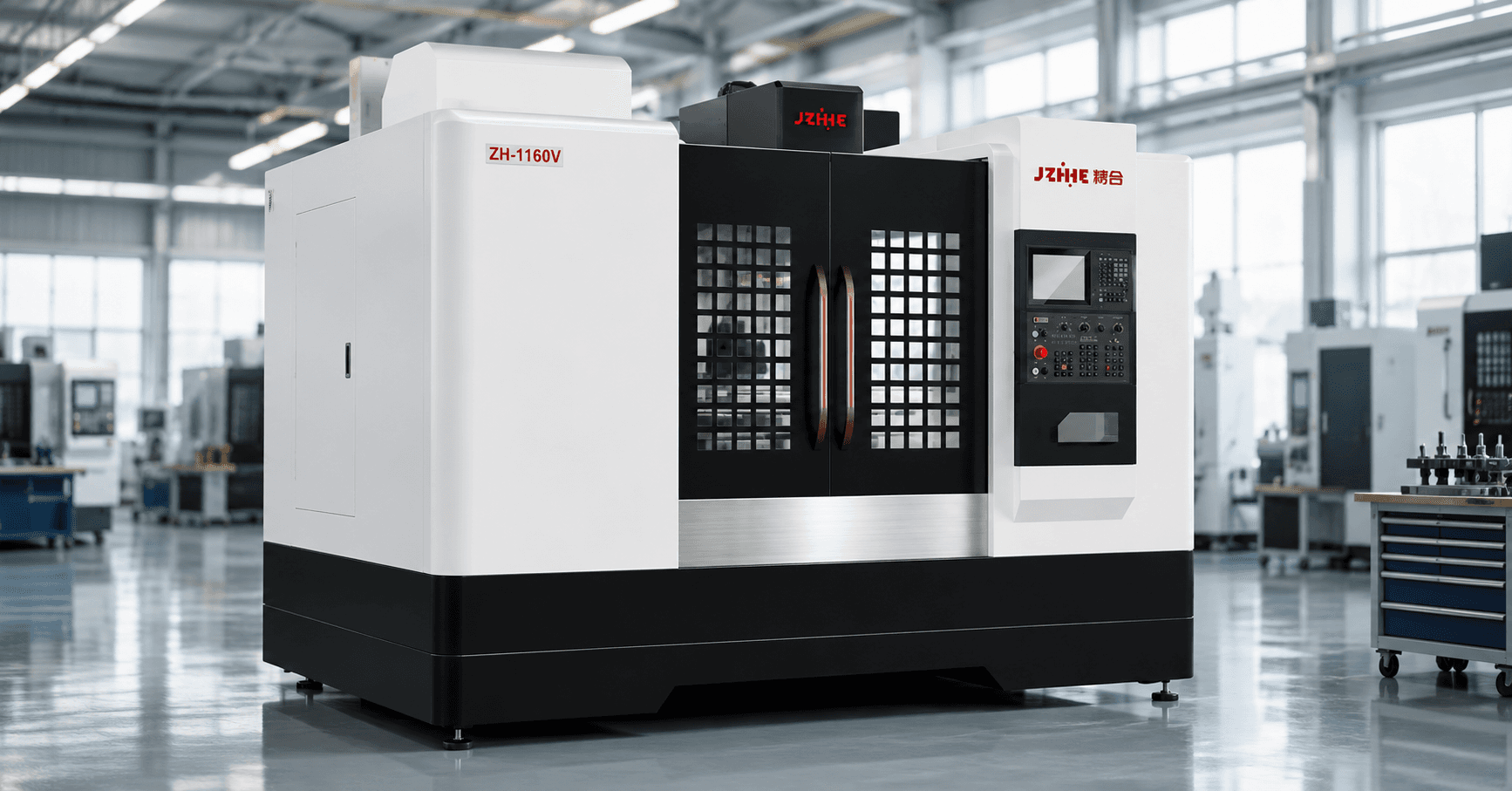
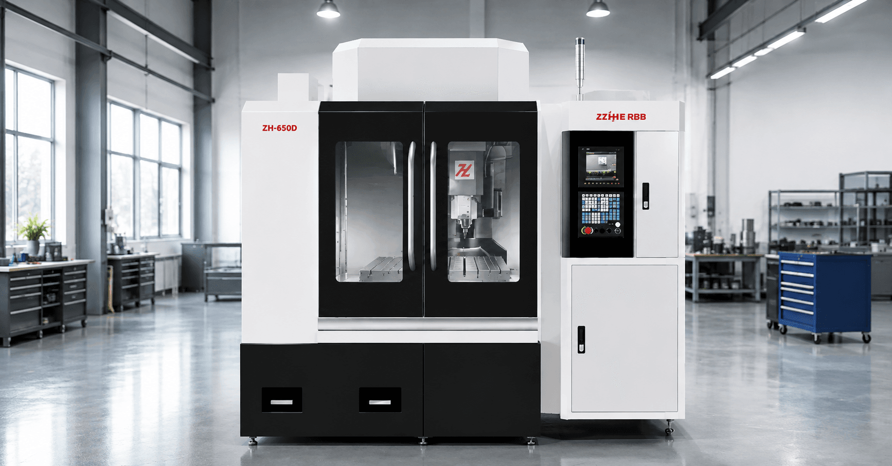
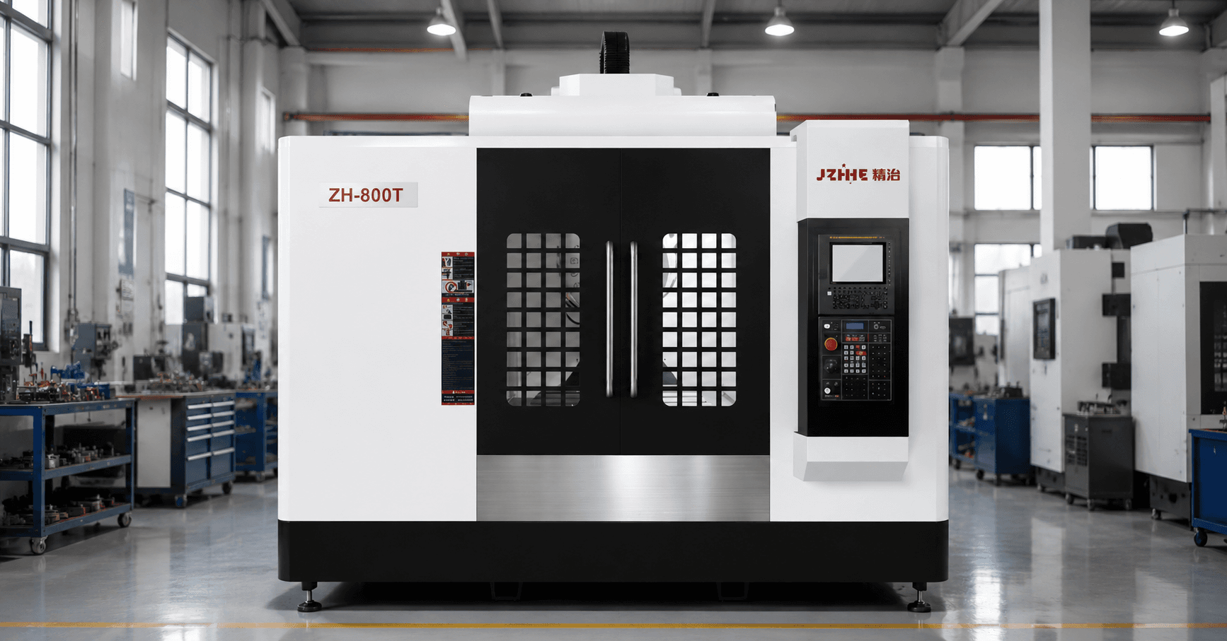
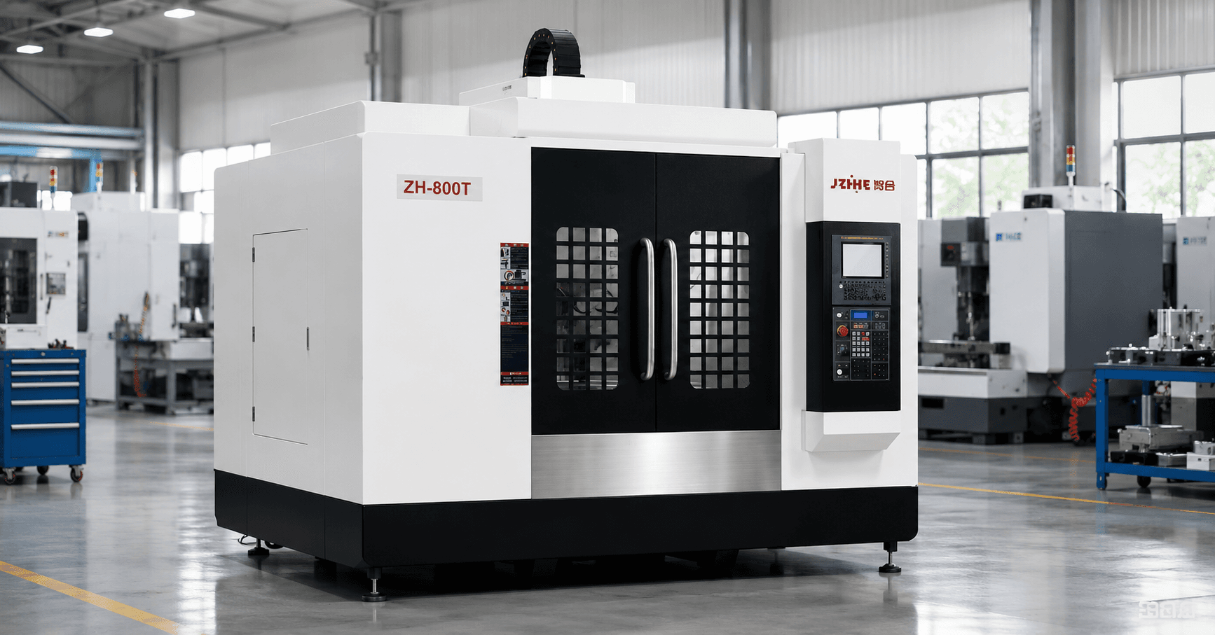
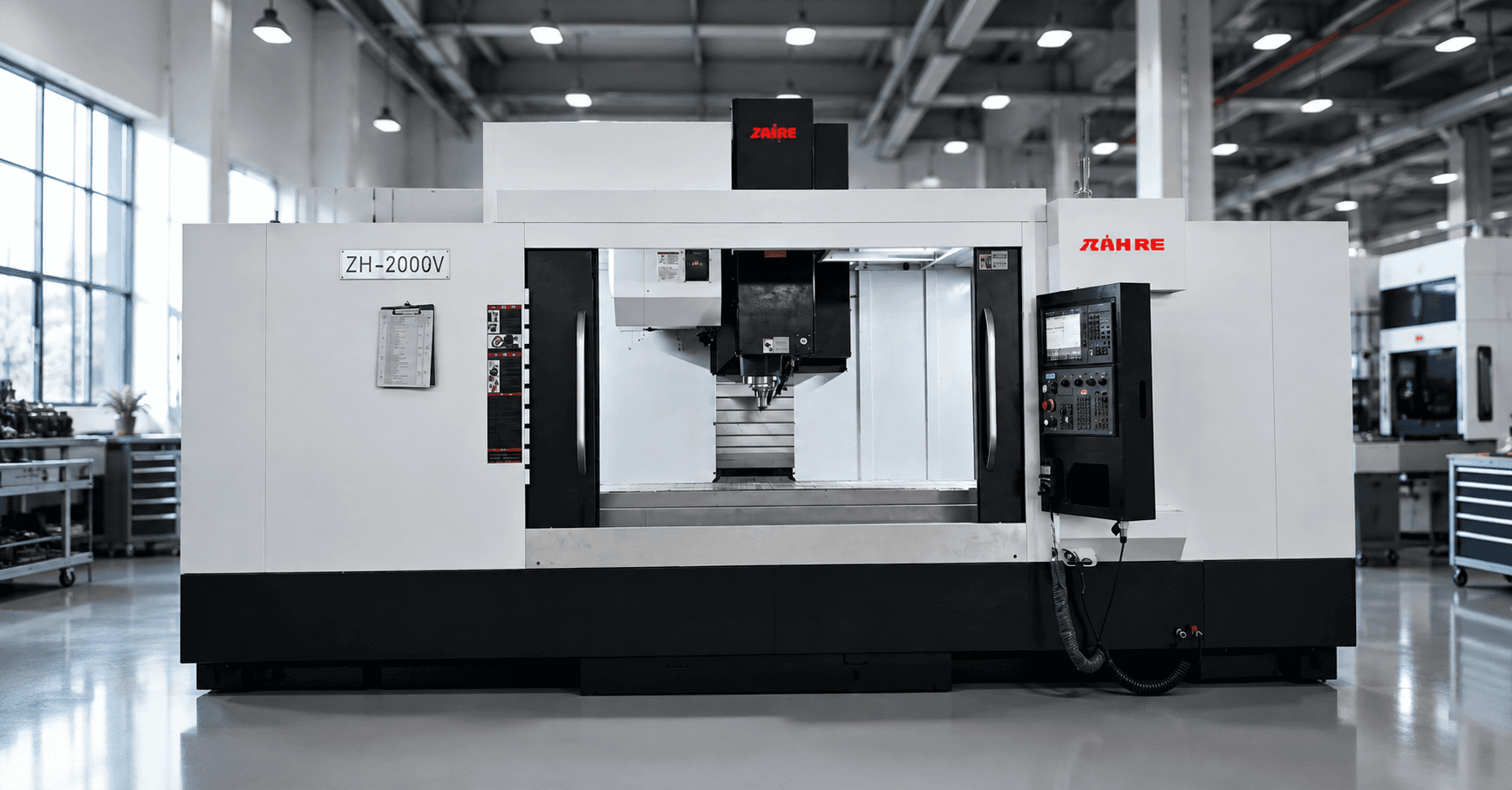
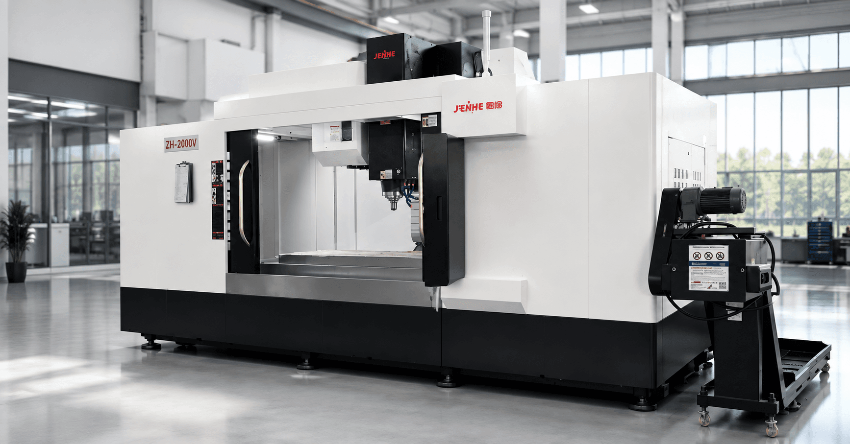
A 3 axis vertical machining center is a strong production choice when the important features can be reached with controlled orientations, practical fixtures, stable tools, and an inspection route that does not erase the machine's cycle advantage. Zhihe CNC uses a setup economics map to decide this from the workpiece outward.
The map is for process engineers and production managers. It separates nominal cutting time from setup, probing, tool changes, inspection, rework, and recovery so the buyer can compare accepted output instead of brochure speed.
Start With the Feature-to-Orientation Map
List every machined face, hole direction, pocket, slot, contour, datum, tolerance, and surface requirement. Assign the orientation that gives the cutter, holder, probe, coolant, and inspection device safe access. Features that share a stable datum and orientation should be grouped before a fixture is designed.
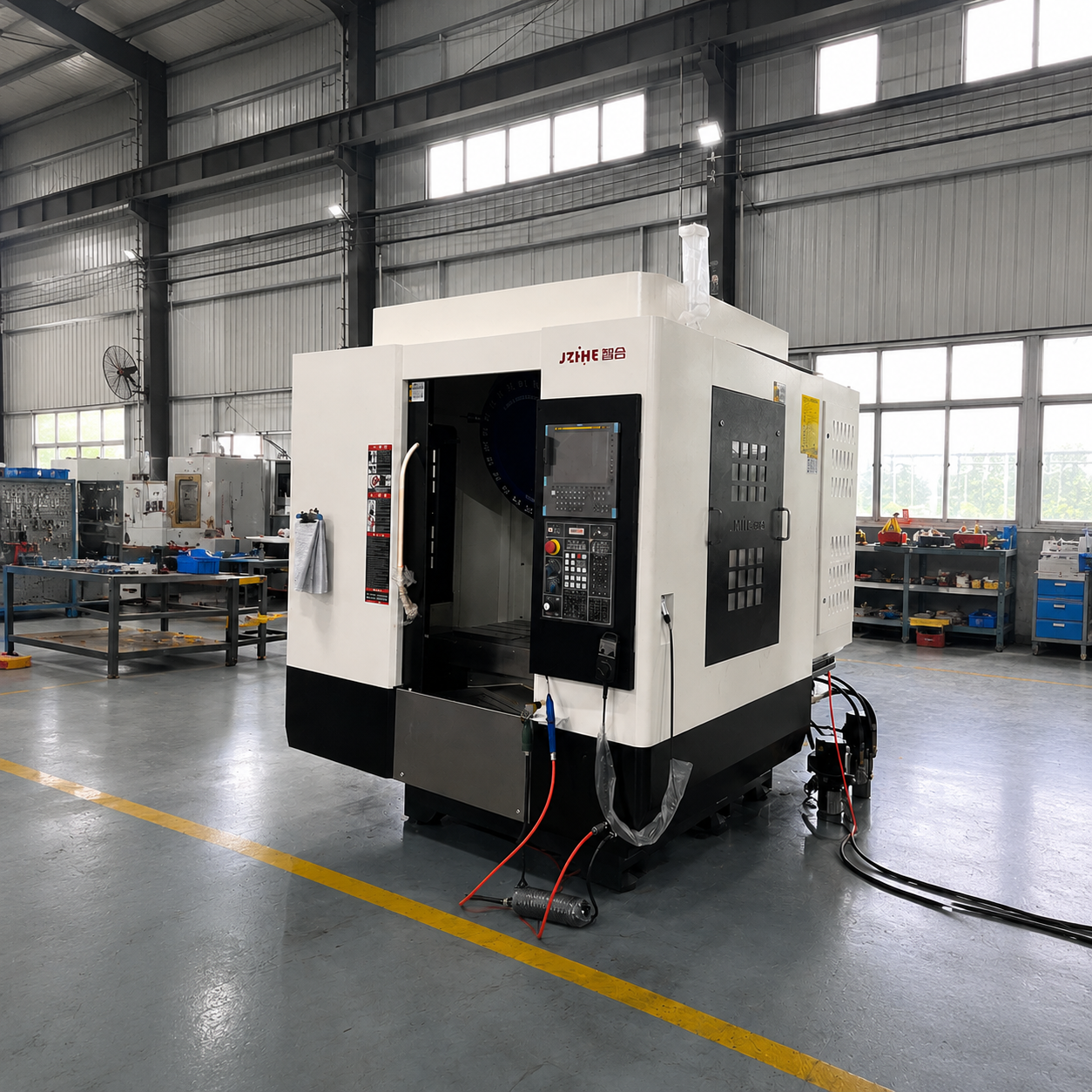
A 3 axis vertical machining center moves X, Y, and Z linearly while the workpiece orientation is normally set by the fixture. This is efficient for plates, molds, brackets, housings, fixture components, and many precision metal parts when top and side features can be organized into a small number of controlled setups.
| Feature condition | Three-axis route | Risk to measure |
|---|---|---|
| Top-face pockets and holes | Single primary setup | Tool reach and chip clearing |
| Opposite-face features | Second controlled setup | Datum transfer error |
| Side holes | Angle plate or additional setup | Fixture access and labor |
| Compound-angle surface | Special fixture or alternate machine | Programming and verification |
| Deep narrow feature | Long tool assembly | Deflection and chatter |
Convert Setups Into an Economics Ledger
For each orientation, record fixture preparation, loading, clamping, cleaning, program selection, tool verification, probing, offsets, dry checks, first-piece inspection, correction, and release. Keep repeat setup and first-time setup separate. A ten-minute cutting cycle can still produce poor output if every batch requires a long approval loop.
The simplest capacity equation is: accepted minutes per part = cutting + tool events + load/unload + setup allocation + inspection allocation + expected recovery + rework allocation. Daily accepted capacity equals available staffed minutes divided by accepted minutes per part, then adjusted for planned maintenance and material availability.
Run a 30-Part Pilot on the 3 Axis Vertical Machining Center
A pilot should include more than thirty identical cutting cycles. Begin with setup release, first-piece approval, normal production, at least one tool-life event, a routine inspection interval, a planned pause, and a controlled restart. Record each timestamp and classify loss as preparation, cutting, tool, quality, material, operator, machine, or information.
Zhihe CNC can use the pilot to compare promised cycle time with accepted-part time. The 3 axis vertical machining center should be evaluated in the same staffing and inspection pattern expected at the plant. If the pilot needs exceptional experts, preselected blanks, or continuous manual intervention, those conditions belong in the capacity conclusion.
Balance Inspection With the Planned Takt
List first-piece, in-process, patrol, and final checks with instrument, location, sample rate, duration, owner, and reaction rule. Compare inspection minutes per batch with the rate at which the machine produces parts. Add cleaning, deburring, data entry, CMM queue, and disposition time.
A 3 axis vertical machining center may produce quickly while accepted inventory grows slowly. Zhihe CNC should help define machine and probing options, while the buyer confirms that gauges, CMM capacity, quality staffing, and release authority can support the output plan.
Create a Repeatable Changeover Standard
Photograph or diagram fixture position, clamp sequence, tool cart, program location, probe routine, offset source, first-piece features, and cleaning points. Pre-stage material, tools, holders, gauges, and documents. Separate internal work that stops the spindle from external work that can be completed while the previous job runs.
Use the same standard during the 3 axis vertical machining center acceptance run. Measure walking, searching, waiting, adjustment, and reinspection. Zhihe CNC and the plant can then target the largest recurring loss instead of treating every changeover minute as unavoidable.
After the standard is stable, audit one normal changeover and one difficult changeover each month. Compare planned and actual tasks, record why deviations occurred, and update only the approved method. This keeps improvement connected to evidence while preventing every operator from creating a private setup sequence. The resulting history also helps distinguish a machine limitation from missing preparation, unclear documentation, worn fixtures, unavailable tools, or delayed quality approval.
Keep the audit sheet beside the fixture record so corrective actions remain visible to the next shift and the next repeat order.
Size the Usable Work Zone, Not Only the Travel
Overlay the blank, fixture, clamps, parallels, tool holder, gauge length, spindle nose, probe, covers, and safe approach planes. Check the highest and lowest Z conditions and the longest tool assembly. Nominal travel does not guarantee that the process fits with safe clearance.
Review the Zhihe CNC vertical machining center range, then validate the exact table, travel, load, spindle interface, and option set against the fixture model.
Match Spindle Duty to the Operation Mix
Separate roughing, drilling, tapping, finishing, and high-speed light cutting. Record material, cutter diameter, flute count, engagement, cutting speed, feed, torque demand, tool interface, gauge length, and expected duty cycle. Peak spindle speed alone cannot describe the usable process window.
Use representative tool assemblies in the trial. A stable short end mill and a long-reach finishing tool create different vibration, runout, balance, and surface risks.
Design the Tool Magazine Around Interruption Risk
Build a tool list by operation, holder, gauge length, life rule, sister-tool need, probe, and spare position. Count common tools across the part family. A magazine that fits one program may still be too small for mixed production or unattended recovery.
Use Probing Where It Removes a Decision
Probing can locate a fixture, confirm a datum, update offsets, check tool length, detect breakage, or measure a feature. It should not be added as a decorative option. Define the exact manual step it replaces, the tolerance of the probing routine, the master artifact, and the response when a result is outside limits.
Validate Accuracy in the Production State
The ISO 10791 machining-centre test series and ISO 230-2 positioning test reference provide useful method context, but the buyer still needs agreed conditions and limits. Record warm-up, environment, leveling, compensation, instrument, program, tool state, fixture, material, sample size, and measurement uncertainty.
Repeat a reference check after sustained cutting and after a representative changeover. Cold geometry, warm production, and post-interruption conditions answer different questions.
Compare Accepted Output Across Alternatives
| Route | Strength | Hidden cost | Upgrade trigger |
|---|---|---|---|
| Three-axis VMC | Simple access and programming | Extra orientations | Datum transfers dominate loss |
| Three-axis plus indexer | Controlled side access | Fixture and rotary limits | Indexed features repeat often |
| Horizontal center | Multi-face and chip flow | Pallet and floor-space needs | Box parts and volume justify it |
| Five-axis center | Complex access and consolidation | Digital and skill dependency | Geometry value exceeds complexity |
Set Axis-Upgrade Triggers Before Buying
Move beyond three axes when repeated datum transfers control scrap, side-feature setups control labor, long tools control quality, compound access controls feasibility, or high-value work-in-process makes consolidation economically important. Do not upgrade only because a machine has more axes.
Respect the Boundary of the Map
The map cannot predict performance without real parts, tools, fixtures, programs, material, coolant, operators, and inspection. It also cannot turn an unsuitable feature orientation into a stable process. Mark assumptions and test the highest-cost uncertainty.
FAQ
Is a three-axis VMC only for simple parts?
No. It can produce complex parts when features are reachable through controlled setups and the tolerance stack remains acceptable.
How many setups are too many?
There is no universal number. Measure labor, queue time, datum transfer, fixture cost, inspection, rework, and volume.
When is an indexer enough?
An indexer can be effective for repeated side features when rotary access, clamping, accuracy, and program control are proven.
Does higher spindle speed always reduce cycle time?
No. Tool diameter, material, engagement, torque, acceleration, chip evacuation, and tool life may set lower practical limits.
Should every part use probing?
No. Use probing when it reliably removes alignment, offset, verification, or recovery work.
How should table load be checked?
Include the blank, fixture, clamps, rotary equipment, and load distribution, not only the finished part.
Can one trial part prove capacity?
No. Use a representative run that includes tool wear, inspection, changeover, and warm-state behavior.
What data should be sent for machine selection?
Send drawings, material, blank, size, mass, tolerances, surface, volume, shifts, cycle, fixtures, tools, inspection, and utilities.
How is three-axis capacity improved?
Standardize fixtures, reduce setup decisions, prepare tools offline, control probing, balance inspection, and remove recurring micro-stops.
What is the strongest acceptance part?
Choose a part or artifact that repeats the access, datum, tool, tolerance, surface, and duty risks that drove the purchase.
Map Your Part Family With Zhihe CNC
To evaluate a 3 axis vertical machining center, send Zhihe CNC your feature map, drawings, material, fixture concept, tool list, tolerance, surface, batch mix, shift plan, cycle target, and inspection route. Use the contact page and compare the three-axis versus five-axis guide.