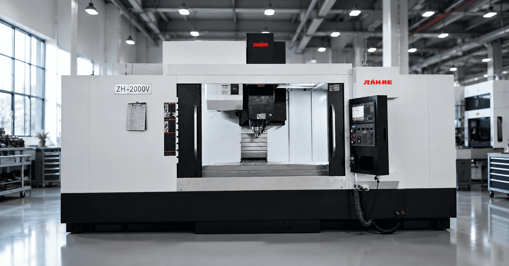
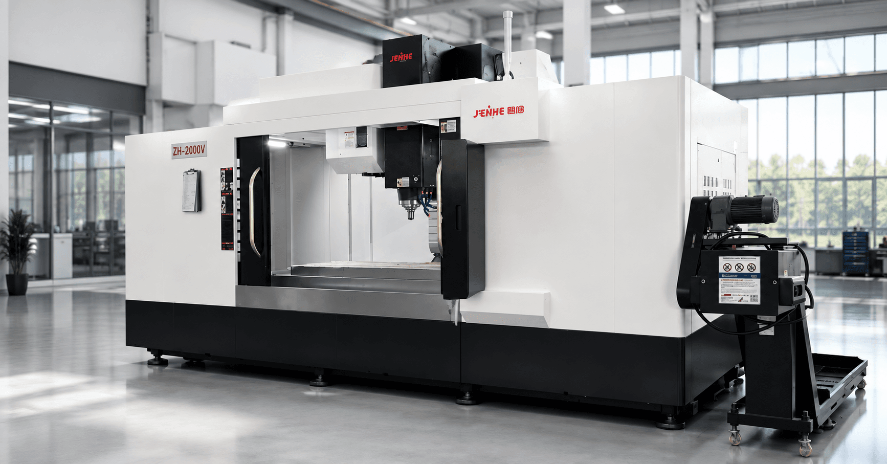
An aluminum drilling tapping center should be judged by accepted parts per shift after chip recovery, tap changes, burr removal, cleaning, inspection, and stoppages are included. Fast rapids and short tool changes can support output, but four losses often decide the result: chips returning to the cut, unstable tap life, burr work moving downstream, and heat shifting the hole pattern.
This diagnostic structure helps buyers locate the dominant loss before specifying equipment. It avoids treating every aluminum component as the same because alloy, temper, wall thickness, hole depth, thread form, fixture, coolant, and cleanliness requirements change the process window.
Loss 1: Chips Return to the Cut
Map every hole, pocket, slot, internal passage, fixture pocket, and surface where chips can collect. Identify blind holes, deep holes, intersecting features, hollow parts, and clamps that block wash flow. Record chip form at the tool, after retraction, around the fixture, and inside the finished component.
Review flute geometry, peck strategy, coolant or minimum-quantity lubrication, through-tool delivery, air use, enclosure wash, fixture drainage, conveyor, filtration, tank access, and final cleaning. The right answer depends on part cleanliness and site rules. High-pressure air may move chips quickly but can create safety, mist, noise, or contamination issues.
Loss 2: Taps Fail Before Their Planned Life
Separate thread failure into entry misalignment, chip packing, lubrication, synchronization, speed, reversal, holder condition, runout, pilot-hole size, material variation, and tool wear. Record tap life by number of threads, not only by hours or shifts. A batch with fewer threaded holes can hide a deteriorating process.
Define a planned-life window and a stop rule. Track torque or load where available, but validate the signal against actual thread quality. Include thread gauge method, sampling frequency, tool identification, replacement reason, and the handling of parts produced since the last accepted check.
Loss 3: Burrs Move Downstream
A short machine cycle can create expensive manual finishing. List entrance burrs, exit burrs, thread-start damage, cross-hole edges, thin-wall breakout, and chips trapped behind burrs. Record deburring time, operator variation, rejected cosmetic surfaces, washing, reinspection, and ergonomic risk.
Test geometry, tool condition, cutting direction, support, breakthrough strategy, chamfering, interpolation, and controlled edge operations. Keep the functional edge requirement explicit. A larger chamfer may remove a burr but violate assembly, sealing, wall, or appearance needs.
| Observed loss | Likely variables | Evidence to collect |
|---|---|---|
| Long stringy chips | Tool geometry, engagement, coolant, material | Chip sample and load trend |
| Early tap replacement | Pilot hole, runout, lubrication, synchronization | Thread count and failure mode |
| Manual edge cleanup | Breakthrough, support, worn tool, edge requirement | Minutes per part and defect type |
| Pattern drift | Warm-up, fixture, coolant, probing, ambient change | Time-sequenced dimensional chart |
Loss 4: Heat Shifts the Hole Pattern
Measure positional relationships across the real batch, not only the first part. Record machine warm-up, spindle duty, coolant temperature, fixture temperature, probe strategy, offset changes, ambient conditions, and time. Thin aluminum parts can also move after unclamping, so define whether acceptance occurs in the clamped or free state.
Use stable datum surfaces and clamp forces. Check whether chips under locators, fixture expansion, repeated re-clamping, or operator cleaning methods change the result. Compensation should have defined limits and ownership; it should not conceal an uncontrolled mechanical or process condition.
Separate Machine Time From Recovery Time
Build a loss ledger with automatic cutting, loading, clamping, tool checks, chip clearing, tap replacement, deburring, washing, inspection, alarm recovery, material waiting, and maintenance. Calculate accepted parts per staffed hour and per available machine hour. This shows whether the next improvement belongs in cutting parameters, workholding, tooling, handling, or downstream operations.
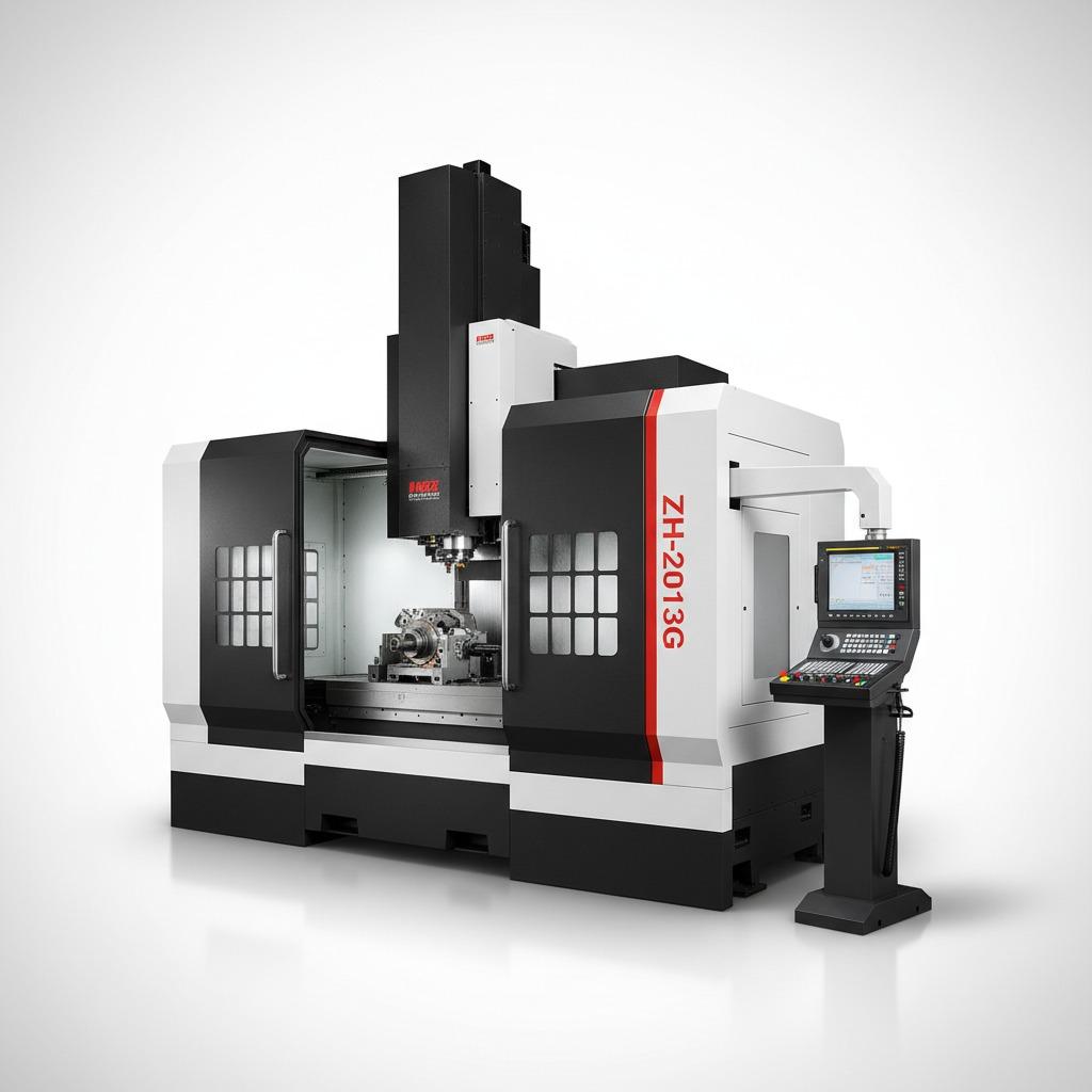
When reviewing an aluminum drilling tapping center, compare the complete part route. A slightly longer automatic cycle can win if it eliminates tap failures, manual burr work, cleaning, and reinspection.
Run a Three-Lot Diagnostic Trial
- Use the intended alloy, temper, blank process, and representative feature map.
- Freeze program, fixture, tools, coolant, measurement, and replacement rules.
- Run three material lots or the most realistic available variation.
- Capture tool life, chip events, burr work, drift, cleaning, stoppages, and accepted output.
- Review the worst period as well as the average and best cycle.
- Define the proven window, warning limits, and remaining risks.
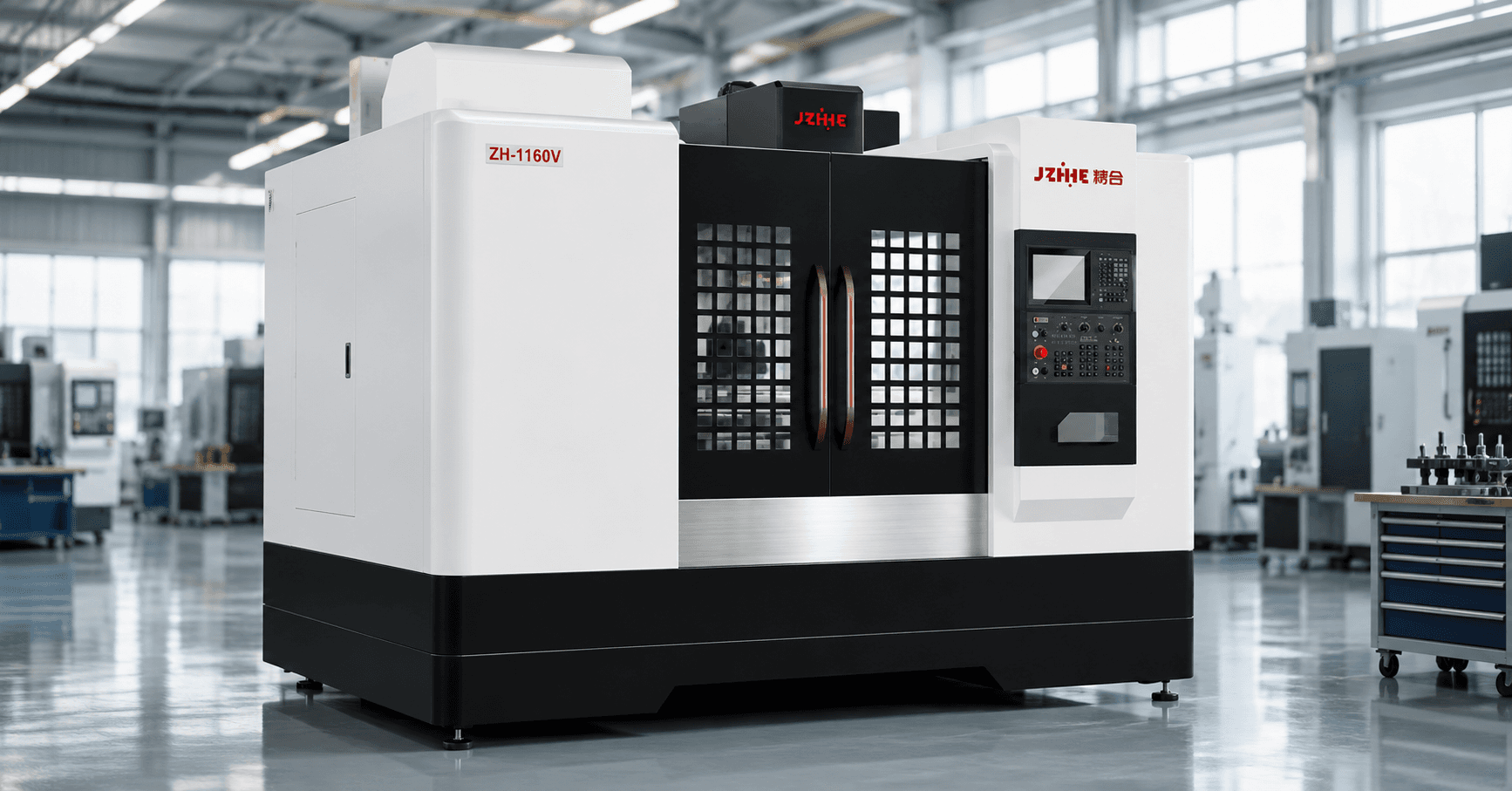
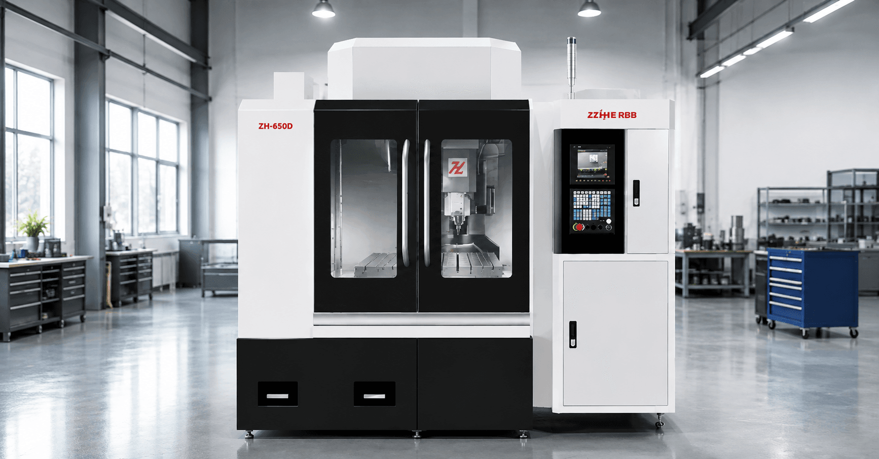
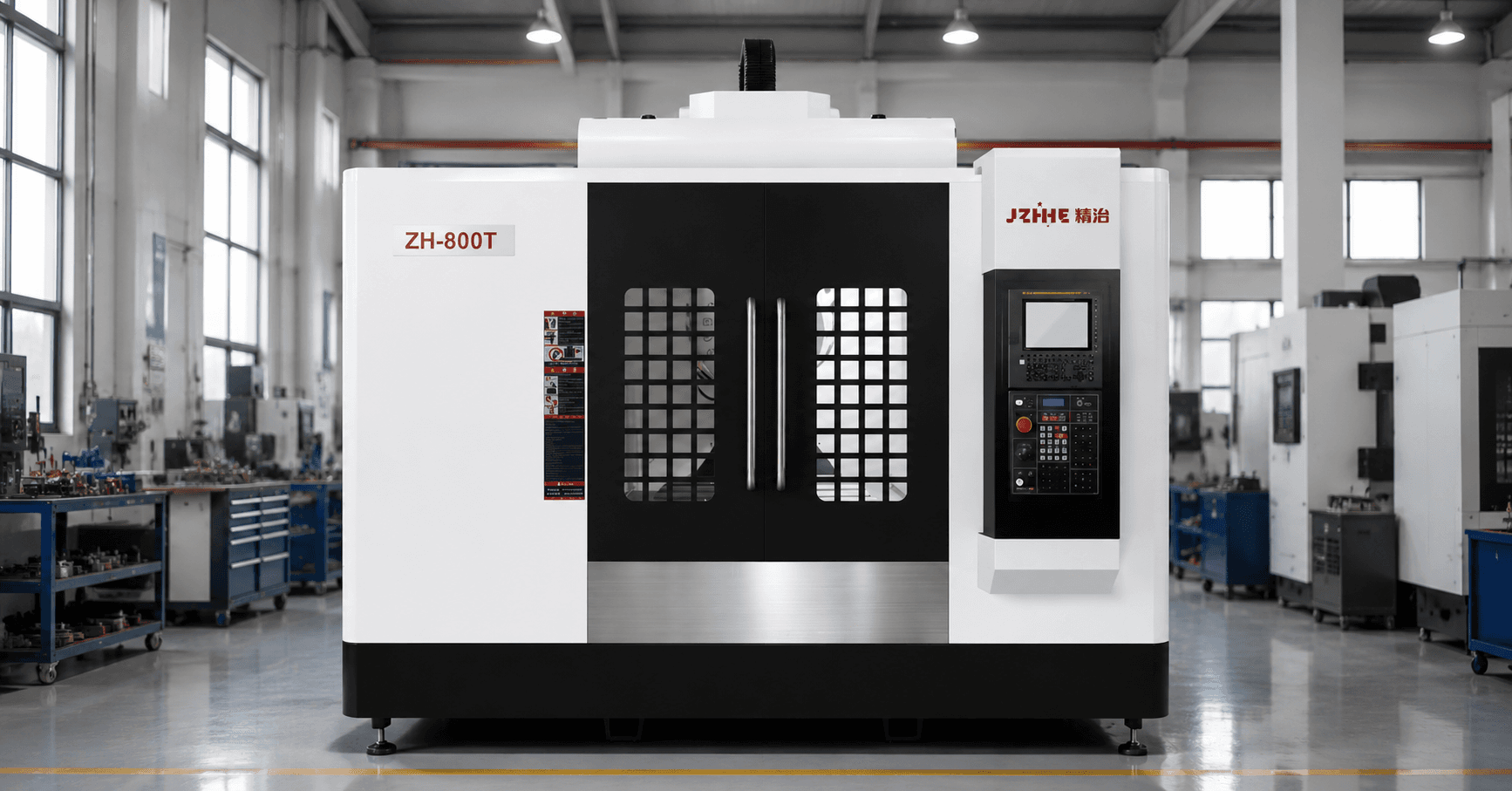
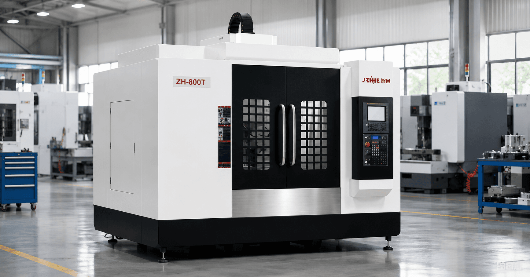
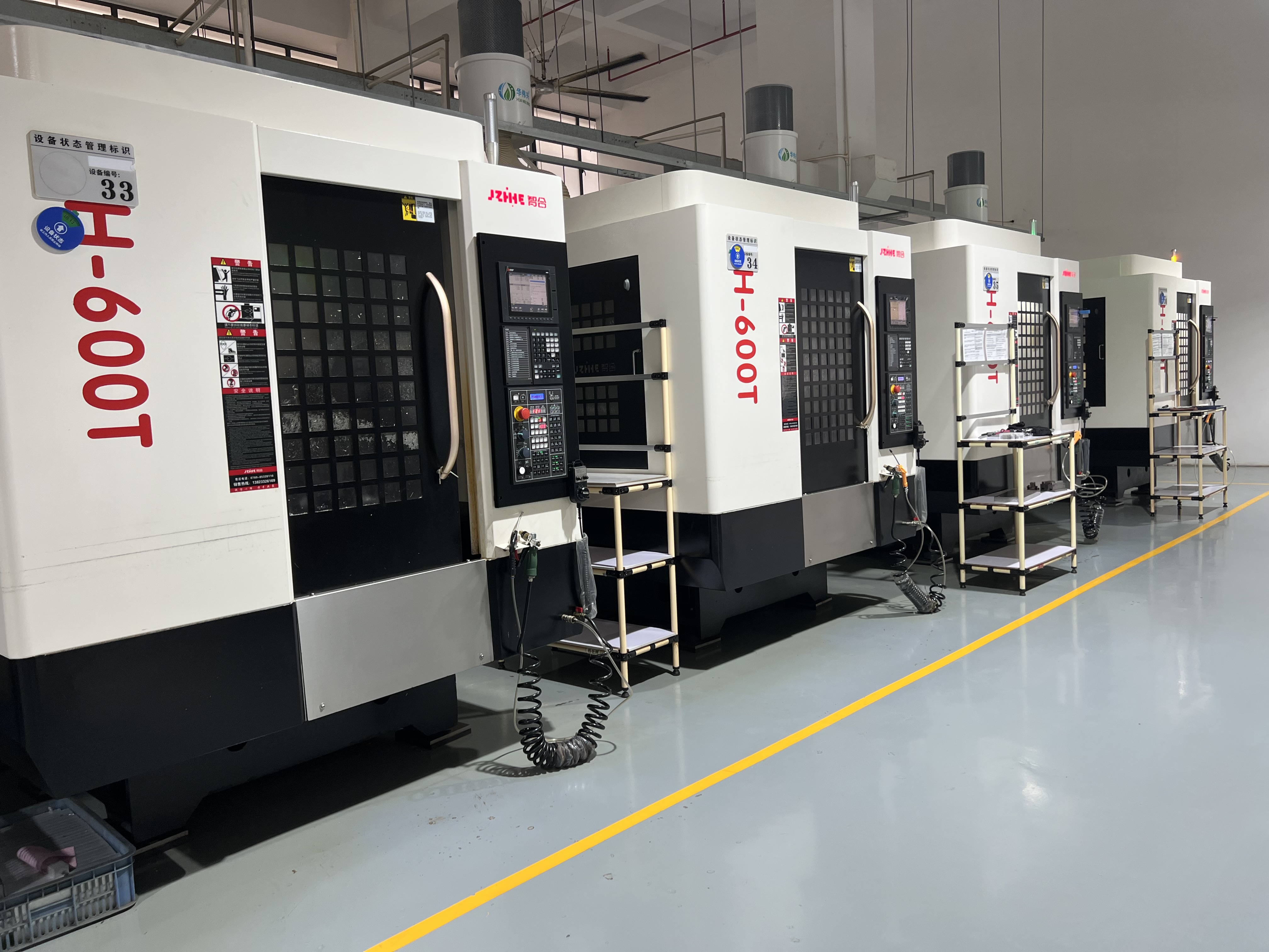
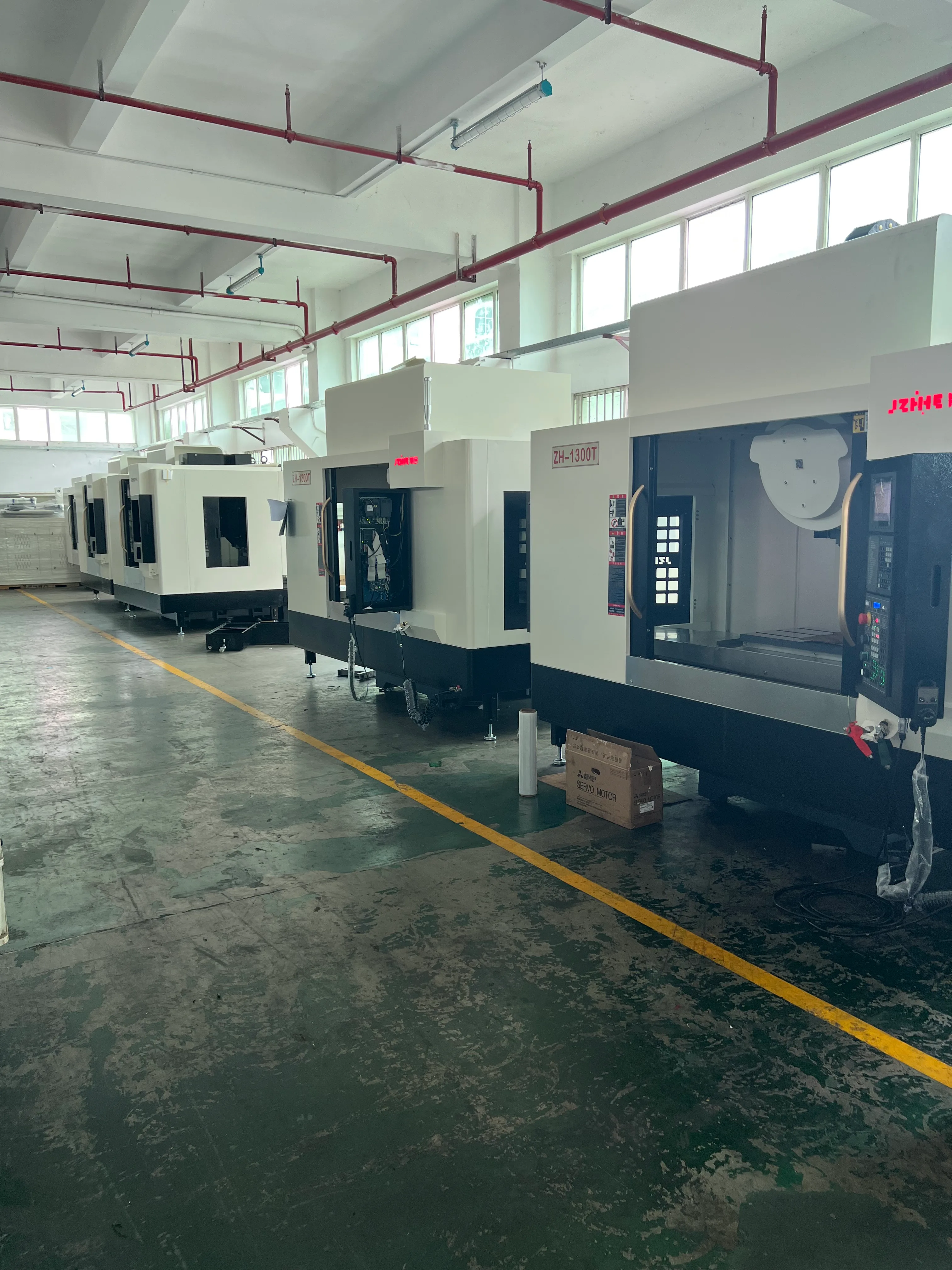
Use the current drilling machining center range to understand the available platform, and review the ZH-600T product page as a configuration reference. Final selection still requires the actual hole map and process target.
When High Speed Is the Wrong Priority
Maximum speed is not the best priority when the part is dominated by deep holes, difficult chip evacuation, demanding thread quality, unstable blanks, heavy fixtures, long-reach tools, low batch volume, or extensive inspection and handling. A different spindle, larger machine, vertical platform, or more conservative process may deliver lower accepted-part cost.
FAQ
Which aluminum alloys should be included in the trial?
Use the actual alloy, temper, stock form, and expected lot variation. 6061 and 6063 can still behave differently by blank condition and feature geometry.
Should rigid tapping be evaluated only by speed?
No. Review synchronization, runout, pilot hole, lubrication, thread quality, tool life, recovery, and the controller-machine configuration.
How is real output calculated?
Count accepted parts over a representative staffed period and include loading, tool work, chip clearing, deburring, cleaning, inspection, stoppages, and maintenance.
Can one sample prove chip control?
No. Chip accumulation, tank condition, tool wear, temperature, and cleaning demand develop over time and across material variation.
Request an Aluminum Cycle Diagnosis
To assess an aluminum drilling tapping center, send the drawing, alloy and temper, blank method, hole and thread map, depth ratios, edge requirements, fixture concept, cleanliness standard, annual volume, batch size, cycle target, and current loss data. Use the contact page to request a process and trial review based on accepted-part output.