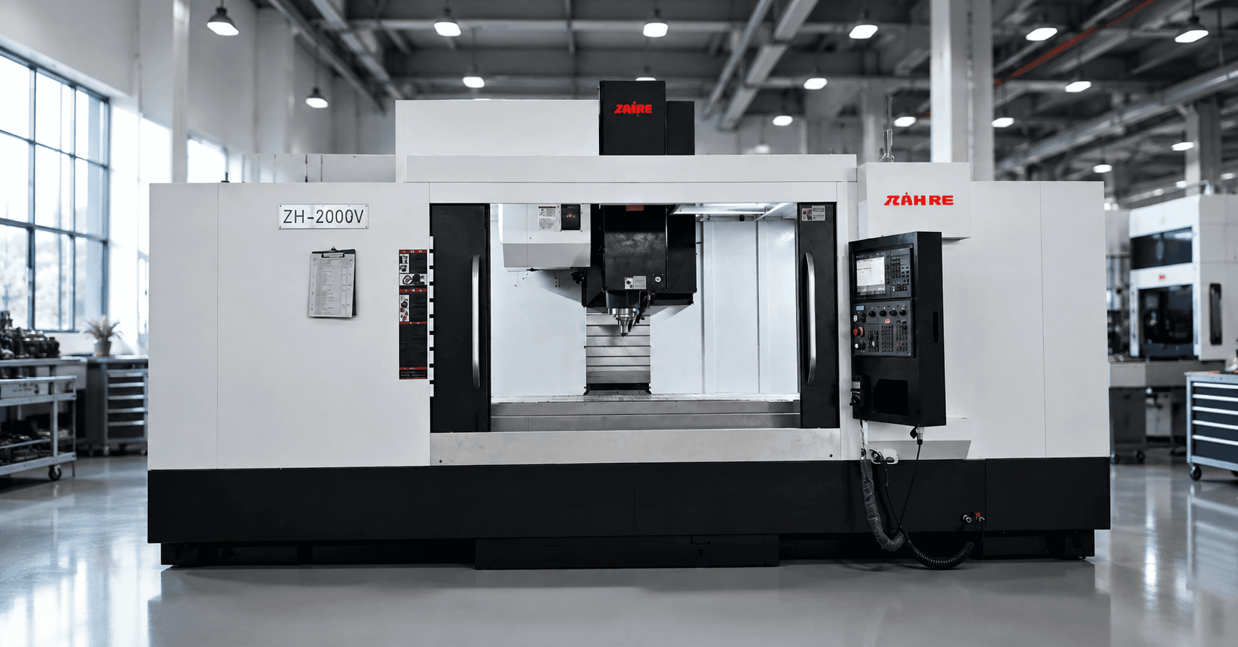
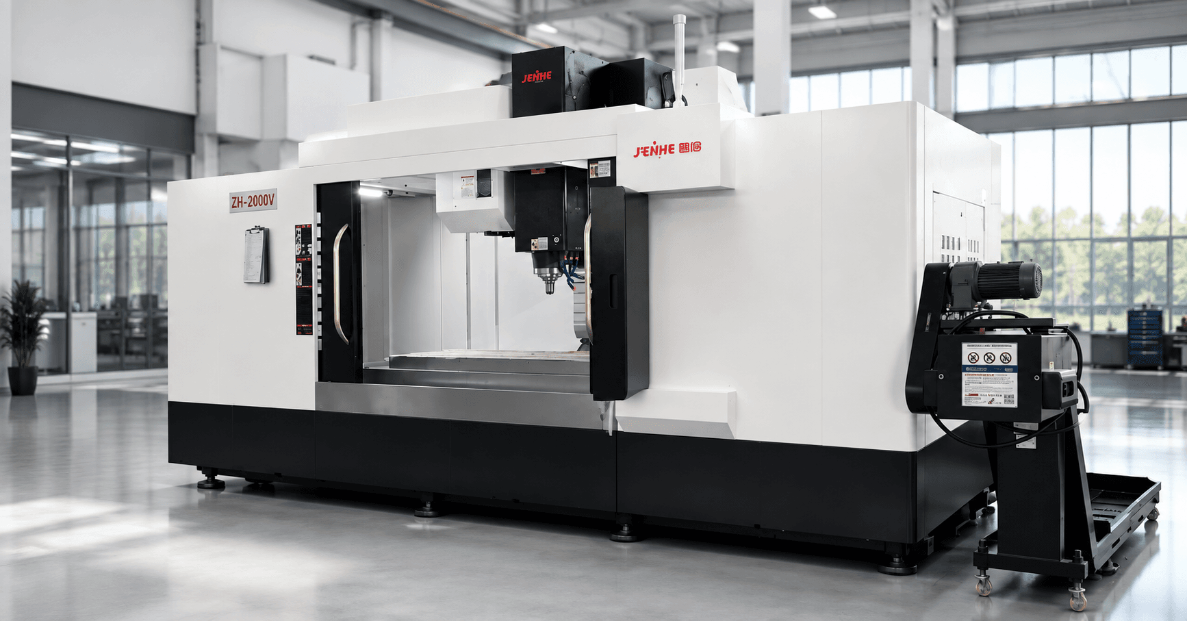
A gantry machining center for large molds should be selected from the mold's machining stages, loaded envelope, and longest stability-critical cycle. Roughing demands productive material removal and chip control. Semi-finishing exposes rigidity and residual stock consistency. Finishing depends on thermal behavior, tool reach, contour accuracy, and surface quality. Deep-hole, cooling-channel, and insert work add another set of access and tooling requirements.
This guide follows the mold through those stages. The goal is to identify which stage controls the machine choice, which requirements belong to tooling or process planning, and which claims must be proven before acceptance.
Stage 1: Define the Loaded Mold Envelope
Start with the largest mold base, fixture, clamps, lifting hardware, and required access. Nominal part length and width do not define usable machine size.
- Add fixture height and support blocks to the Z-axis stack.
- Check spindle nose, holder, and longest tool at the highest and lowest surfaces.
- Allow clearance for clamps, probing, chip guards, and tool approach.
- Confirm table load using the workpiece, fixture, and accessories together.
- Review door, roof, crane, and loading access before the machine layout is frozen.
If the workpiece rotates or is repositioned, verify every orientation. A machine that fits the blank may still fail to reach a deep cavity or clear a tall clamp during finishing.
Stage 2: Decide What Roughing Requires
Roughing defines cutting load, chip volume, spindle duty, tool size, and the structural forces applied over long cycles. Record the mold material, hardness, blank condition, stock allowance, largest cutter, depth and width of cut, removal target, and expected continuous cutting time.
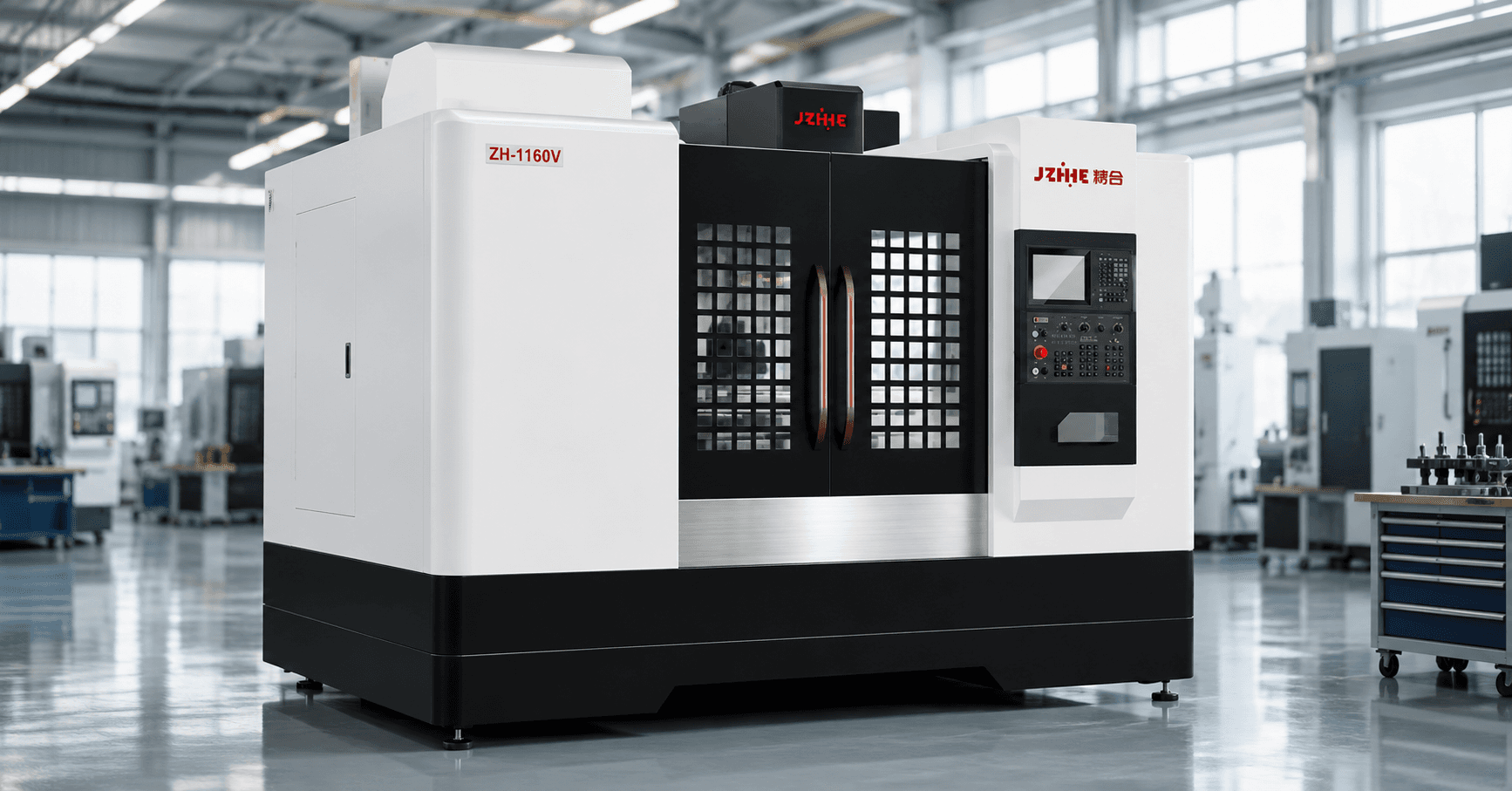
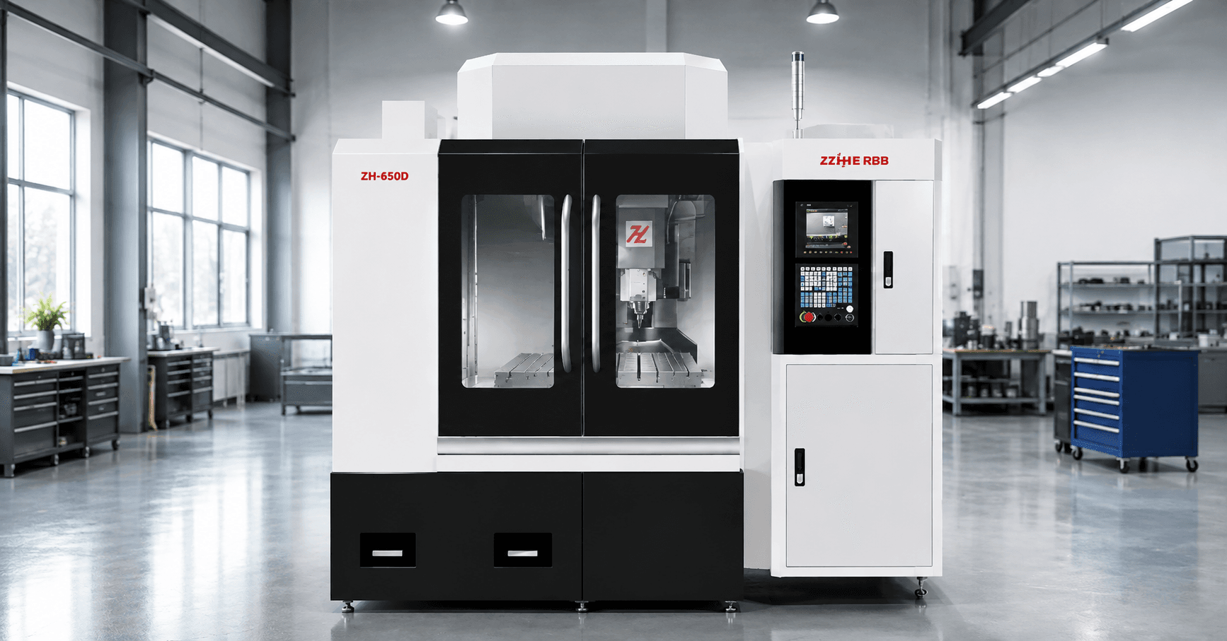
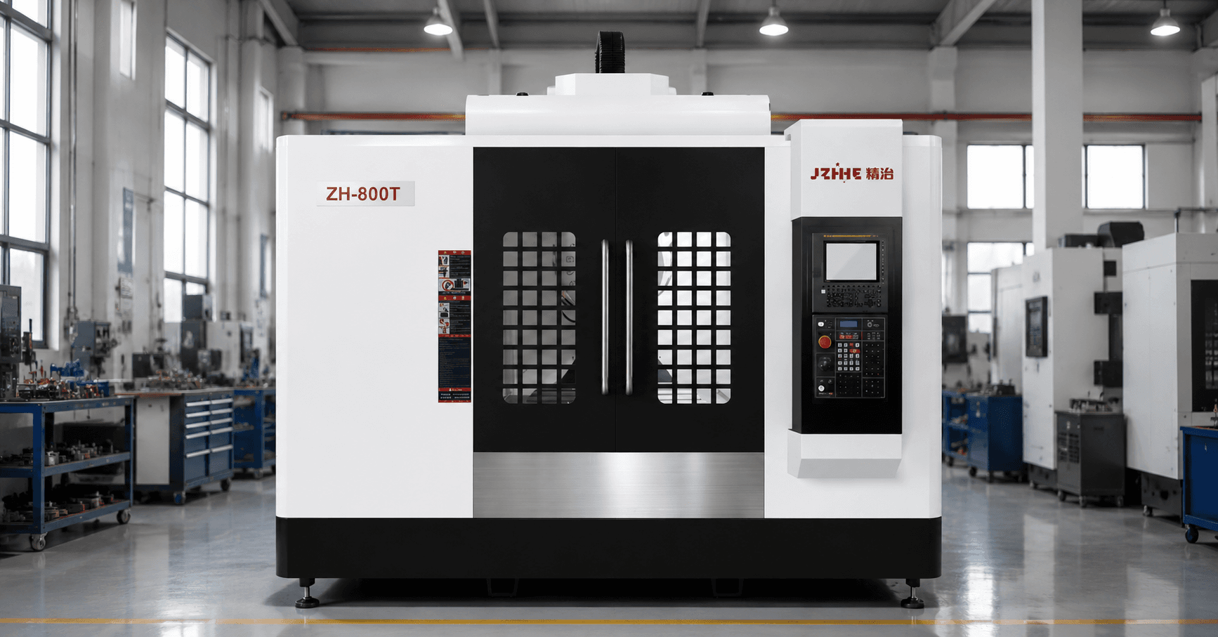
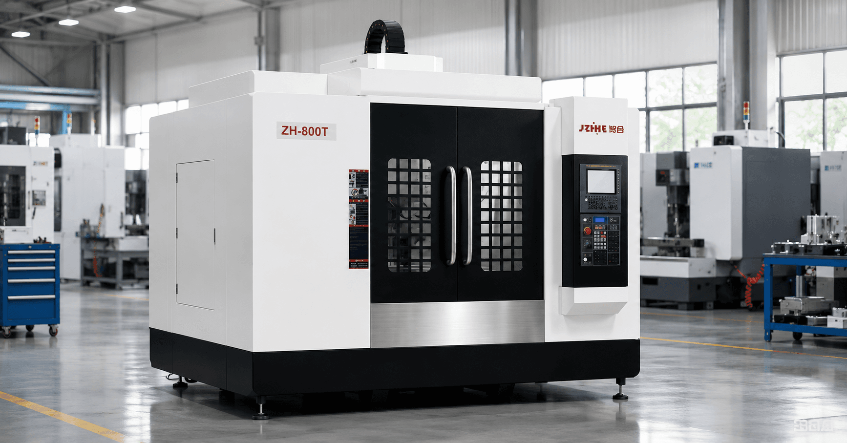
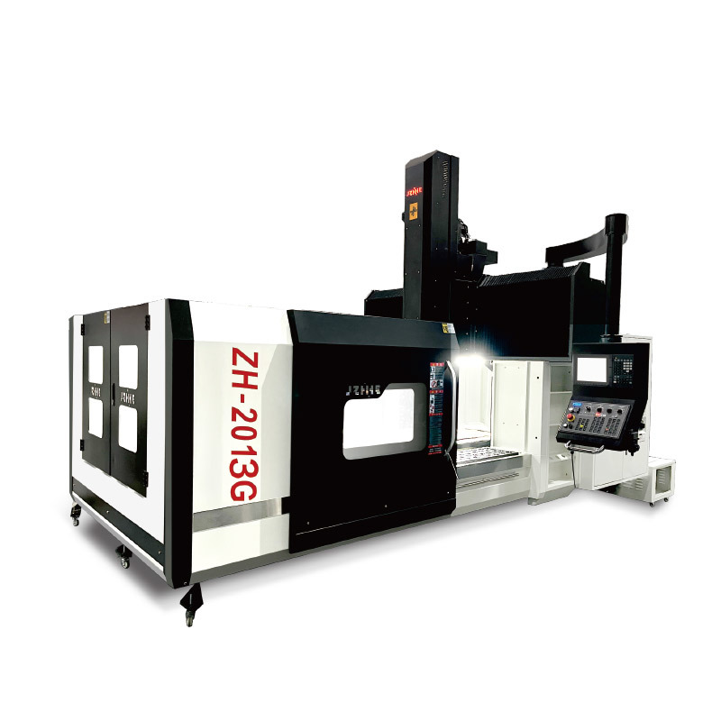
Zhihe CNC describes its gantry machining center platform as a fixed-beam structure with stationary columns and crossbeam while the worktable moves along X. The published product description also identifies heavy-duty roller linear guides on X and Y and a four-sided rectangular hard-rail arrangement on Z. These design statements should be connected to a cutting demonstration using the buyer's material and tool strategy.
Roughing decision
If roughing is the controlling stage, prioritize verified spindle duty, torque behavior, structural rigidity, chip evacuation, coolant delivery, toolholder interface, and stable stock removal. Do not buy a higher speed option when the process is limited by torque, tool engagement, or chip evacuation.
Stage 3: Protect Semi-Finishing Stock
Semi-finishing creates the stock condition that finishing depends on. Uneven residual stock increases finishing load, tool deflection, local heat, and surface variation.
Review:
- Datum and support strategy after roughing releases material stress.
- Whether the workpiece leaves the machine between roughing and semi-finishing.
- How stock is measured and how offsets are corrected.
- Tool reach, holder interference, and deflection in deep areas.
- How chips are removed from cavities before the next toolpath.
A process that produces a good final surface on one test region can still fail across the complete mold if semi-finish stock is inconsistent.
Stage 4: Match Finishing to Thermal and Contour Risk
Finishing often contains long continuous programs with small stepovers, changing tool orientation, and deep reaches. The relevant questions extend beyond static positioning accuracy.
| Finishing risk | What to specify | How to prove it |
|---|---|---|
| Thermal drift | Warm-up, environment, spindle cooling, compensation, cycle length | Measure features across a representative long run |
| Contour variation | Controller functions, look-ahead, acceleration, CAM and post | Cut representative curves and transitions |
| Tool deflection | Reach, holder, cutter, engagement, stock consistency | Inspect depth-related size and surface changes |
| Surface mismatch | Toolpath zones, rest machining, tool changes, offsets | Check blend areas under agreed lighting and measurement |
| Machine vibration | Structure, spindle condition, tool balance, cutting data | Use the actual tool assembly and material |
Selected Zhihe CNC models are described as supporting positioning accuracy up to +/-0.005 mm and repeatability up to +/-0.003 mm depending on series, model, travel, and configuration. For a large mold, require the proposed model's exact inspection report and a test that reflects the mold size and cycle.
Stage 5: Account for Holes, Inserts, and Support Operations
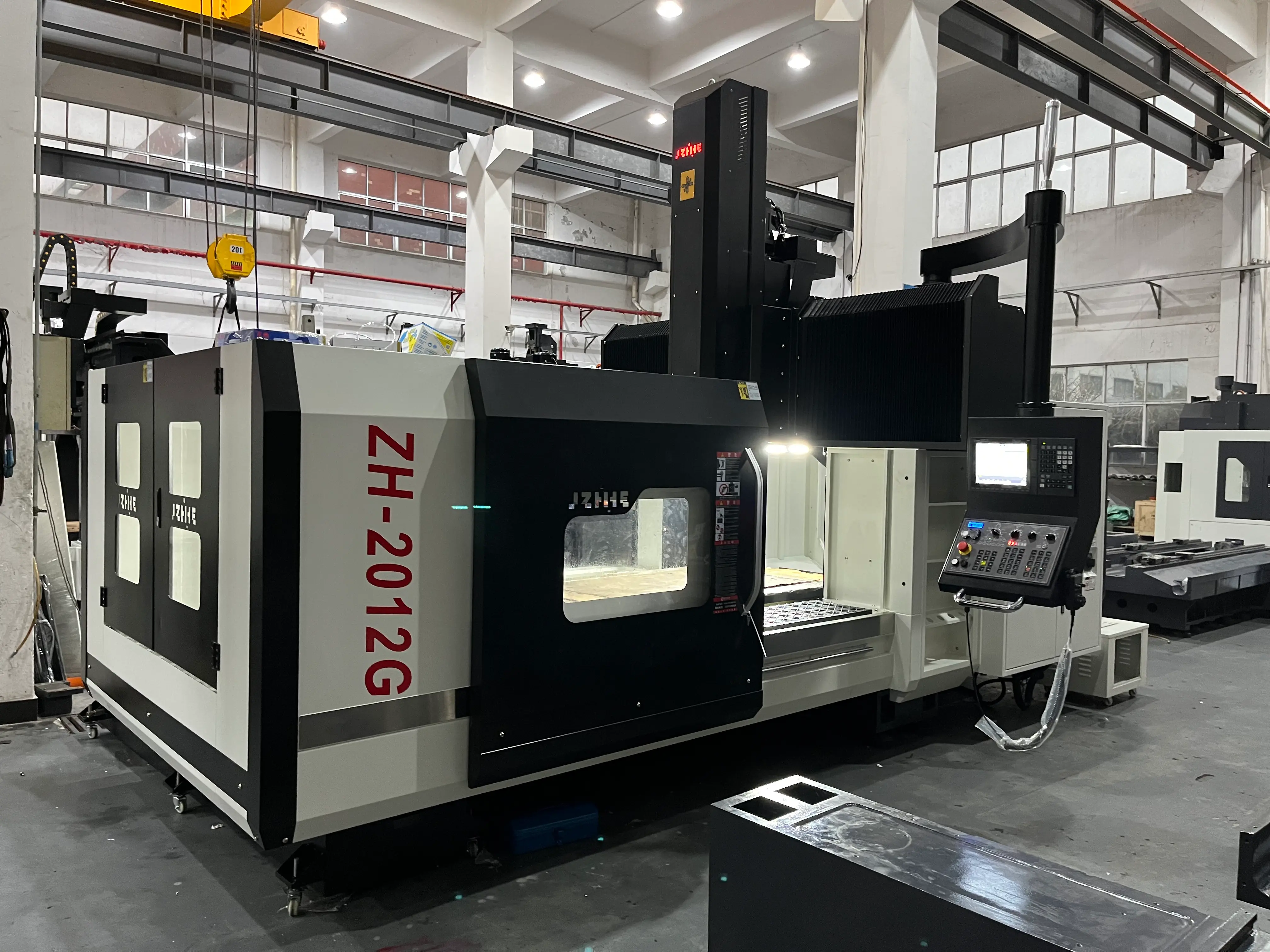
Large molds may require water lines, ejector holes, guide features, insert pockets, tapping, angled access, and manual verification. List every operation expected on the gantry machine and every operation that will move to another machine.
This prevents an expensive machine from being judged only on cavity milling while secondary operations create repeated setups and queue time. If special heads, long tools, probing, or additional axes are proposed, define the exact operations they solve and the new collision, calibration, and training requirements they introduce.
Use a Gantry Machining Center for Large Molds Decision Tree
- Does the loaded mold fit with full tool access? If no, increase travel or redesign the fixture and process split.
- Does roughing control the project? If yes, prove spindle duty, rigidity, chip flow, and material-removal stability.
- Does finishing control the project? If yes, prove thermal behavior, contour performance, tool reach, and surface consistency over time.
- Are multiple setups damaging relationships? If yes, review travel, access, probing, and setup reduction before adding precision claims.
- Is the machine underused because support work remains outside? If yes, compare an integrated process with a specialized multi-machine route.
- Can the supplier demonstrate the controlling stage? If no, treat the quotation as unverified.
Compare Process Time Across the Complete Mold
Machine price should be compared against complete mold lead time, not only cutting speed. Include programming, setup, roughing, stress release, re-clamping, measurement, semi-finishing, finishing, drilling, bench work, correction, and rework risk. The separate gantry machining center price guide provides a line-item method for normalizing supplier quotations.
| Alternative | Potential advantage | Potential cost |
|---|---|---|
| One larger gantry platform | Fewer transfers and broader in-machine access | Higher capital concentration and possible scheduling bottleneck |
| Separate roughing and finishing machines | Stage specialization and parallel work | Datum transfer, handling, queue, and duplicate fixture needs |
| Standard gantry plus special attachments | Broader operation coverage | Calibration, collision, training, and maintenance complexity |
| Outsource rare operations | Avoid underused options | Supplier lead time, transport, and quality coordination |
Prove the Machine With a Stage-Based Trial
A useful trial does not need to machine an entire commercial mold, but it should reproduce the controlling risks. Build a test piece or representative workpiece with roughing load, deep reach, semi-finish stock, contour transitions, critical holes, and an extended finishing section.
Agree on material, blank, tools, holders, CAM, post-processor, coolant, warm-up, environment, measurement, and acceptance limits before cutting. Record corrections and manual interventions. A trial result without its process conditions is difficult to reproduce after delivery.
Prepare a Mold-Specific RFQ
Include the largest and typical mold drawings, materials and hardness, loaded weights, fixture concepts, current routing, roughing stock, largest tools, deepest features, required surfaces, critical tolerances, hole and thread schedule, annual workload, preferred stage split, factory foundation, crane access, utilities, and delivery destination.
Ask for a compliance matrix, layout, spindle and tool data, process-stage proposal, trial method, accuracy reports, foundation and installation requirements, training, maintenance, spare parts, and a written list of exclusions.
FAQ
Should the largest mold always define the machine?
Only if that mold must be processed internally and its workload justifies the capacity. Compare the cost of a larger platform with outsourcing or splitting rare oversized work.
Is static positioning accuracy enough for mold finishing?
No. Finishing also depends on thermal behavior, controller and contour performance, tool reach, tool balance, CAM, stock consistency, and cycle length.
What should a roughing trial demonstrate?
It should demonstrate the proposed spindle, holder, cutter, material, engagement, chip evacuation, and sustained cutting behavior under documented conditions.
Why evaluate semi-finishing separately?
Because finishing quality and time depend on consistent residual stock. Semi-finishing reveals fixture, stress, tool-reach, and process-control problems before the final toolpath.
What installation information is required?
Confirm machine weight and dimensions, foundation, floor loading, leveling points, crane and access route, power, air, coolant, extraction, temperature expectations, and maintenance clearance.
Request a Mold-Stage Evaluation
To evaluate a gantry machining center for large molds, send Zhihe CNC the mold envelope, loaded weight, material, roughing and finishing route, deepest features, critical surfaces, annual workload, and factory conditions. Use the contact page to request a stage-based machine and trial proposal.